
Operation Manual
Assembly and Operating Instructions Ver. 2 11/12 (2288)
10
allow a snug but free spinning fit. The castor fork swivel allows the wheelchair
to be steered. An adjustment locknut is located under the castor cap. If the
locknut is too tight, the wheelchair will be difficult to steer.
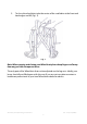
7. Wheel lock assembly
These are used to hold the wheelchair in a stationary position, and are fitted
on either side of the wheelchair. They should not be used when the
wheelchair is moving or to slow it down. They should always be applied
together.
To operate, push the brake lever forward towards the front of the wheelchair.
This will immobilize the wheelchair. To release the brake, move the lever
towards the rear of the wheelchair.
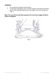
8. Cross Bar
Operation of the cross brace permits the wheelchair to be opened and closed
easily. It should be inspected at regular intervals for signs of wear and
bending.
9. Folding Backrest Device
Push down the hinge to fold down the backrest. Automatically lock when pull
up the backrest handle. This device is to enhance the storage feature.
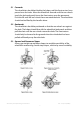
10. Quick Release Wheels
To aid transportation, the rear wheels can be removed by pushing the middle
section of the wheel and pulling to release. To refit, reverse the procedure.
Always make sure the wheels are fully connected before use.
11. Tyre pressure and inflation
For Wheelchairs that are fitted with pneumatic tyres they should be inflated
with a manual operated pump. Under no circumstances should a powered or
compressed air pump be used. The tyre pressure should be tailored for
optimum user comfort and ease of Wheelchair use. We recommend a tyre
pressure of 35psi (241KpA) for comfort. However, do not exceed the maximum
tyre pressure stated on the side wall of the tyre. This may differ slightly
between tyres, but is typically:
• 65 psi (487 KpA) for 24” self-propel wheels
• 40 psi (275 KpA) for 12½” transit wheels