MXL USER MANUAL
MXL User manual Release 1.19 MXL, with all its versions (Strada, Pista, Pro, Pro05) belongs to the new generation of AIM data acquisition systems for car/bike races. Equipped with a beautiful and wide display, easy to use, multi-functional and fully configurable, it fits any need and can record in detail driver’s and vehicle performances. MXL is part of AIM Total Racing Solution, that includes also Race Studio 2 software to configure the logger and download its data.
MXL User manual Release 1.19 INDEX 1 – MXL kits, optional and part numbers ................................................................ 3 1.1 – MXL Strada kit, optional and part numbers ........................................................................ 3 1.2 – MXL Pista kit, optional and part numbers ........................................................................... 4 1.3 – MXL Pro05 kit, optional and part numbers..........................................................................
MXL User manual Release 1.19 0 1 – MXL kits, optional and part numbers AIM developed different MXL kits to fit any situation. Here below a description of each standard kit with the related optionals. Warning: MXL Pro is out of production, replaced by MXL Pro05. 7 1.
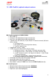
MXL User manual Release 1.19 17 1.2 – MXL Pista kit, optional and part numbers MXL Pista standard kit: X10MXLC000000 • • • • • • • • MXL Pista (1); Complete wiring with power, RPM signal and ECU CAN/RS232 interface (2); USB cable for PC interface and data download (3); 1 speed sensor + cable (4); 2 temperature sensors + cable (5); Infrared lap transmitter with external power cable (6); Infrared receiver with 90 cm cable (7); Race Studio 2 Software CD and MXL user manual (8).
MXL User manual Release 1.19 18 1.
MXL User manual Release 1.19 8 1.4 – MXL Expansions • • • • • • • • • • • Channel expansion Data Hub with 40 cm cable: Data Hub with150 cm cable: DaVid Slave Expansion: DaVid Slave Expansion cameras PAL protocol: LCU-ONE CAN: LCU-ONE CAN+Analog MemoryKey (except for MXL Strada): GPS Module with 125 cm cable: GPS Module with 400 cm cable: TC Hub (CAN): X08CHEXUC X08HUB010 X08HUB150 X01DVMKSE000 X01CAMPAL X08LCU03K0 X08LCUKAOCRS X50MEPC00 X40GPS3BM125 X40GPS3BM400 X08UTCCTC Please visit www.
MXL User manual Release 1.19 1 9 2 – MXL installation and power 2.1 – How to install MXL To install MXL follow these instructions: • choose a place where the display is not in contact with oil or fuel. • be sure that the logger is not installed close to heat sources.
MXL User manual Release 1.19 43 2.2.1 – the GND For a correct powering and signal stability it is suggested to connect the cable labelled GND out coming from MXL power wiring to the vehicle chassis earth. www.aim-sportline.
MXL User manual Release 1.19 19 2.3 – How to connect MXL to the ECU MXL can sample data out coming from the ECU using the proper CAN/RS232 interface cable. To know if the vehicle ECU is supported by MXL – and for further information concerning ECU and AIM loggers connection – refer to the related documentation freely downloadable from AIM corporate website at www.aim-sportline.com download area, ECU section.
MXL User manual Release 1.19 20 2.4 – How to sample the RPM signal MXL can sample the RPM signal in different ways: • from the ECU via CAN bus or RS232; • from the ECU through a square wave signal (from 8 to 50 V); • from the coil: low voltage input (from 150 o 450 V). 30 2.4.1 – Sampling the RPM via CAN bus/RS232 To sample RPM via CAN bus/RS232 refer to ECU connection chapter. 31 2.4.
MXL User manual Release 1.19 • Connect the interface black cable – labelled “GND” – to the vehicle chassis earth (refer to GND paragraph of this user manual for further information). • Connect the adapter cable labelled “RPM-ECU 4-50 V” to the RPM signal out coming from the ECU. The images here below show a not square RPM signal on the left and a filtered one on the right. 33 2.4.
MXL User manual Release 1.19 The images below show on the left a non filtered unstable coil signal and on the right a filtered one. 11 2.5 – How to connect MXL analog channels MXL is equipped with numerous analog and digital channels and their number changes depending on the model. MXL Strada/Pista models have 8 analog channels and 3 digital channels: • RPM • 1 speed channel • Lap Time. MXL Pro model has 8 analog channels and 6 digital channels: • RPM • 4 speed channels • Lap times.
MXL User manual Release 1.19 21 2.6 – How to install and power transmitter and receiver AIM provides a range of devices for lap time detection. MXL works with infrared transmitter and a receiver only. 34 2.6.1 – Infrared transmitters AIM lap transmitter is show here below.
MXL User manual Release 1.19 To activate High/Low power mode it is necessary to unscrew the back of the transmitter case as shown here below on the left. The image here above on the right shows possible working mode. The transmitter comes set in low power mode: see images on top on the right. To set high power mode insert both clips in the jumper: image bottom on the right. WARNING: verify the number of transmitters installed on the track before installing one’s own.
MXL User manual Release 1.19 44 2.6.2 – The infrared transmitter The infrared receiver has to “see” the transmitter installed on the side of the track. Install it with the receiver eye looking at the transmitter. The figure here below shows the receiver eye Be sure that the receiver has a continuous line with the transmitter on the right side of the vehicle as shown on the image here below. www.aim-sportline.
MXL User manual Release 1.19 22 2.7 – How to connect MXL to the GPS Module MXL can be connected via CAN bus with AIM GPS lap timer. It allows to record lap and split times with no need of infrared transmitter/receiver.
MXL User manual Release 1.19 45 2.7.1 – GPS Module and the Lap timer function This new MXL expansion allows to show and record lap and split times without infrared receivers and transmitters. A GPS Module (with firmware version 35.13 or later) connected to an MXL (with firmware version 14.86.22 or later) is all you need. The first thing to do is fixing lap and split points giving the GPS Module instructions that are correct and coherent with the configuration set. This allows it to record lap times.
MXL User manual Release 1.19 23 2.8 – How to connect MXL to the MemoryKey MXL can be connected via CAN bus to MemoryKey. It allows to download data without connecting the logger to a PC. The connection has to be done as follows: • MXL Pista: connect the MemoryKey to 5 pins Binder 712 female connector on the back of the logger (pin 1 = CAN+ ; pin 4 = CAN-) • MXL Pro/MXL Pro05: connect MemoryKey to 22 pins Deutsch type connector using the proper cable labelled CAN Exp (pin 1 = CAN+; pin 4 = CAN-).
MXL User manual Release 1.19 2 3 – MXL display Here below explanation of the which information are provided by MXL display, and where. Please refer to Race Studio Configuration user manual, that can be downloaded from www.aim-sportline.com download area, software section for any further information about MXL configuration.
MXL User manual Release 1.19 24 3.1 – Forecast Lap time Forecast Lap Time is an algorithm predicting, in real time, current lap time before the lap is completed. MXL compares each 0.1 km (0.16 miles) the current lap with a reference one and – using this information – foresees the final lap time.
MXL User manual Release 1.19 25 3.2 – Alarm led and shift light rpm GEAR AL 1 SPEED AL 4 km/h AL 2 AL 5 AL 3 AL 6 << >> MENU ok quit MEM VIEW The ten top led (shift light) of the display are connected to engine RPM; values corresponding to each led are set via software or via keyboard. See the paragraph concerning keyboard function or Race Studio Configuration user manual for further information on the subject.
MXL User manual Release 1.19 3 4 – MXL: software, driver, configuration, transmission, download, online, maintenance MXL easily connects to a PC thanks to the USB cable and can be configured only using Race Studio 2, the powerful software – supplied free of charge – developed by AIM to configure its loggers and analyze data. MXL standard kit includes the USB cable and Race studio 2 and USB driver installation CD. WARNING: the logger can be configured only after software and driver installation.
MXL User manual Release 1.19 4 5 – MXL keyboard function MXL keyboard has got a number of functions: data recall and deletion, back-light, date and time, GPS Module, calculated gears, shift lights, demo mode. 13 5.1 – Data recall When a test session is over it is possible to recall data stored in MXL memory. To enter data recall mode press MEM button, highlighted here below.
MXL User manual Release 1.19 Using buttons “<< / >>” it is possible to scroll all laps and runs. “<>” buttons scroll times and values starting from best lap. In case the system is set to capture split times, they are always shown on the static string and it is possible to distinguish them from lap times because time value is anticipated by an “S”. The above image shows the static string with – from left to right: • • • • run number: 2; lap number: 5; split number (S): 1; split time: 0.04.07. www.
MXL User manual Release 1.19 26 5.2 – Other keyboard functions MXL keyboard manages all these functions not managed by the software and allows also to set the shift lights. The following paragraph explains how to manage the single controls: they are listed in the same order they appear pressing “MENU”. 36 5.2.1 – Backlight Press “MENU”. The display shows: Night Vision on/off. Press “OK/MEM” to enable/disable the backlight and then “Quit/VIEW” to confirm.
MXL User manual Release 1.19 40 5.2.4 – Date and time Press four/five times (depending on whether there is a GPS Module connected or not) “MENU”. The display will show: set date and time.
MXL User manual Release 1.19 46 5.2.6 – System Information Press seven/eight times (depending on whether there is a GPS Module connected or not) “MENU”. The display shows Firmware version on the left and logger serial number on the right. 42 5.2.7 – Demo mode It is possible to see MXL working mode also without any sensor connected. It is just enough it is powered. Switch the logger on and press “MENU/<<” and “>>”. Demo mode starts. To stop it switch the logger off. www.aim-sportline.
MXL User manual Release 1.19 5 6 – MXL memory Each MXL is equipped with a non-volatile RAM memory, whose dimensions change depending on the logger model: • MXL Strada 128 kb • MXL Pista/Pro 8 Mb • MXL Pro05 16 Mb The round memory records up to 500 laps in two blocks made of 250 laps; so, when lap 501 is recorded laps from 1 to 250 are deleted. This means that the last 250 laps are always in the memory of the logger and that lap memory does never fill up. 14 6.
MXL User manual Release 1.19 6 16 Appendix “A” – Technical drawings A.1 – Loggers pinout N.rev. / Rev. N. Descrizione / Description Data / date Firma / Sign Contr. da / Ckd.
MXL User manual Release 1.19 N.rev. / Rev. N. Descrizione / Description Data / date Firma / Sign Contr. da / Ckd.
MXL User manual Release 1.19 N.rev. / Rev. N. Descrizione / Description Data / date Firma / Sign Contr. da / Ckd. by MXL Pro pinout 22 pins Deutsch female connector 37 pins Deutsch female connector 22 pins Deutsch female connector pinout Rif. / Ref.
MXL User manual Release 1.19 N.rev. / Rev. N. Descrizione / Description Data / date Firma / Sign Contr. da / Ckd. by MXL Pro05 pinout 22 pins Deutsch female connector 37 pins Deutsch female connector 22 pins Deutsch female connector pinout Rif. / Ref. Q.tà / Q.
MXL User manual Release 1.19 27 A.2 – MXL Strada/Pista wirings N.rev. / Rev. N. Descrizione / Description Data / date Firma / Sign Contr. da / Ckd. by MXL Strada standard cable 6 - 0.5 mm unifilar cables AMP 12 pins female connector 6 5 3 2 1 12 11 10 9 8 7 4 AMP 12 pins female connector pinout Contact insertion view Non cabled channels table Channels Cable Colour AMP 12 pin Rif. / Ref. Q.tà / Q.
MXL User manual Release 1.19 Q.tà / Q.ty Progettato da / Designed by 4 pins Binder 719 female connector Solder termination view 3 2 16 15 14 13 12 11 10 9 12 pins AMP female connector Contact insertion view 8 12 11 10 9 7 12 pins AMP female connector Contact insertion view 4 1 2 6 5 4 3 1 8 7 6 5 4 3 2 1 10 Teflon cables N. articolo / Item N. Materiale / Material Contr. da / Ckd. by Contr. da / Ckd. by 12 pins AMP female connector 16 pins AMP female connector Rif. / Ref.
MXL User manual Release 1.19 N.rev. / Rev. N. Descrizione / Description Data / date Firma / Sign Contr. da / Ckd.
MXL User manual Release 1.19 N.rev. / Rev. N. Descrizione / Description Data / date Firma / Sign Contr. da / Ckd. by Not cabled channels table Channel Cable colour Rif. / Ref. Q.tà / Q.ty Progettato da / Designed by AMP 12 pin Connection Length Power Red Black 2 1 Vb ext (9-15 VDC) GND 500 mm RPM White 8 RPM Coil - Square Wave 500 mm CAN White Blue 4 3 CAN+ CAN- 500 mm RS232 White Blue 6 5 RS232RX RS232TX 500 mm N. articolo / Item N. Materiale / Material Contr. da / Ckd.
MXL User manual Release 1.19 A.3 – MXL Pro05 wirings 6 5 4 4 pins - Binder 719 female connector pinout Contact insertion view 3 2 4 Rif. / Ref. Q.tà / Q.ty Progettato da / Designed by A 37 pins Deutsch male connector Heatshrink A Ringale cover 90° bended Heatshrink 1 1 Contr. da / Ckd.
MXL User manual Release 1.19 N.rev. / Rev. N. Descrizione / Description Data / date Firma / Sign Contr. da / Ckd.
MXL User manual Release 1.19 N.rev. / Rev. N. Descrizione / Description Data / date Firma / Sign Contr. da / Ckd. by Channels cabled with Binder 719 Continuation table of sheet 2 Channel Binder pin Cable colour Deutsch pin Connection Length 320 mm Lap 1 2 3 4 white black red blue 37 28 14 37 Lap in GND + VB Lap in Speed 1 1 2 3 4 white black red n.c. 36 28 14 Speed 1 GND + VB Speed 2 1 2 3 4 white black red n.c.
22 pins Deutsch male connector Rif. / Ref. A Progettato da / Designed by Q.tà / Q.ty Contr. da / Ckd. by Racing Data Power 1 Materiale / Material Approvato da / Approved by Nome file / File name N. disegno / Drawing N. 04.554.24 www.aim-sportline.com 7 8 18 22 11 12 9 19 10 20 13 3 2 Data / Date Rev. / Rev. 4 2 5 pin Binder 712 female connector pinout solder termination view 5 1 3 4 pins Binder 719 female connector pinout Solder termination view 4 1 9 - 1x0.
MXL User manual Release 1.19 N.rev. / Rev. N. Descrizione / Description Data / date Firma / Sign Contr. da / Ckd. by Channels ending with Binder 719 Channel Binder Pin Cable colour Deutsch pin Connection USB 1 2 3 4 white black red n.c. 7 9 8 USB D+ GND USB D- Speed 3 1 2 3 4 white black red n.c. 5 11 10 Speed 3 GND + VB Speed 4 1 2 3 4 white black red n.c.
22 pins Deutsch male connector A Rif. / Ref. Q.tà / Q.ty Progettato da / Designed by Contr. da / Ckd. by Racing Data Power 1 Ringale cover Materiale / Material Approvato da / Approved by Nome file / File name N. disegno / Drawing N. 04.554.24/A www.aim-sportline.com 7 8 18 22 20 13 11 12 9 19 10 14 3 2 Data / Date Rev. / Rev.
MXL User manual Release 1.19 N.rev. / Rev. N. Descrizione / Description Data / date Firma / Sign Contr. da / Ckd. by Channels ending with Binder 719 Channel Binder Pin Cable colour Deutsch pin Connection USB 1 2 3 4 white black red n.c. 7 9 8 USB D+ GND USB D- Speed 3 1 2 3 4 white black red n.c. 5 11 10 Speed 3 GND + VB Speed 4 1 2 3 4 white black red n.c.
MXL User manual Release 1.19 29 A.4 – USB Cable N.rev. / Rev. N. Descrizione / Description Data / date Firma / Sign Contr. da / Ckd. by USB cable for data download - 3.5 mm stereo Jack Cable lenght 2500 mm 3.5 mm stereo JACK Shielded USB cable Standard USB connector Pin connection USB connector pinout Top view 4 3 2 1 D+ GND GND D+ DN.C. D- USB connector pinout front view 4 Rif. / Ref. 3 Q.tà / Q.ty Progettato da / Designed by 2 1 N. articolo / Item N. Materiale / Material Contr.