
Instructions


12
On high value inductors, such as transformers designed to work at 50/60Hz, the self resonant
frequency can be below the higher test frequencies of the LCR 400. Above the self-resonant
frequency these inductors will appear as a lossy capacitor. Due to the distributed nature of these
parasitics, the equivalent values of the resistance and capacitance change with frequency.
The leaked magnetic field, whilst usually negligible in the case of torroids, laminated core
inductors and pot core inductors, can be significant with axial inductors like RF chokes and ferrite
rod antennae. This means that the inductance of a device with a ‘leaky’ magnetic field can vary
considerably depending upon the characteristics of any conducting or magnetic material close to
the device. Any conductive material within the device’s field will contain induced currents that can
in turn have the effect of reducing the apparent inductance of the component. Conversely any
ferro-magnetic material in the immediate area of the component can have the effect of increasing
the apparent inductance. In extreme cases the inductance of a component can appear to vary
depending upon its distance above the connectors and steel case of the LCR400.
Low value inductors (<100uH) are best measured at 10kHz whilst high values >25H should be
measured at 100Hz. The instrument warns if a measurement is outside its maximum accuracy
range by flashing the units annunciator; if accuracy can be improved by changing the
measurement frequency the frequency annunciator will also flash, see Display section.
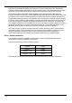
Series / Parallel connection
The LCR400 provides the capability of measuring the series or parallel equivalent circuit
parameters of resistors, capacitors and inductors.
In Auto mode the bridge uses the following models.
Resistor
Series
Inductor
Series
Capacitor <1µF
Parallel
Capacitor >1µF
Series
These will provide the parameters that will match data sheet values for most components.