
User Manual

Page 42
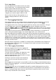
7.5 Level Offset and Compensation Tables
These functions are only available when the upgrade option U01 is fitted - see section 6. They
enable the amplitude scaling to be offset to match external attenuation or gain, or to add
frequency dependent amplitude compensation tables to match transducers or antennae. A
description of the menu keys used to control the function is given in section 4.5.4.
7.5.1 Dynamic Range and Maximum Signal
Adding offset or compensation can create confusion as to the maximum and minimum
signal levels that can be viewed.
This could result in the instrument being in amplitude overload even when the displayed
amplitude value is apparently within the instrument range. Where an offset is set to a large
negative value (to compensate for an external gain element) there is a danger that the absolute
maximum signal level could be exceeded resulting in damage to the instrument - see section
3.1.2.
Offset levels and compensation tables should therefore be used with care !
7.5.2 Creating and using Compensation Tables
Compensation tables are normalised files of amplitude versus frequency that are used to
compensate for frequency related non-linearity in antennae or transducers.
The files contain lists of up to 100 frequency/amplitude points. When a file is used by the
instrument, linear interpolation is employed between the points.
Every point on the trace is then changed by the amount calculated from the interpolated
compensation table. Note that this could result in parts of the trace being outside of the
graticule area.
Compensation Tables must be created outside of the instrument using PSA-Manager software -
see section 6.1.7.
Compensation Table files have the extension .CMP and are located in the folder named
TABLES. Files can be transferred using either a USB Flash drive, or by direct connection to the
USB port of a PC. See section 5 for an explanation of copying and transferring files.
A compensation table file is loaded in a similar way to other types of file using a File Recall
screen - see section 5.4 .
Note that compensation tables and limit patterns are both placed in a folder called Tables and
can therefore appear within the same File Utilities screen. It is possible to toggle between the
two file types by pressing the key marked Tables (toggle).
7.6 Limit Lines & the Limits Comparator | Creating Limit Patterns
These functions are only available when the upgrade option U01 is fitted - see section 6. A
description of the menu keys used to control the function is given in section 4.5.5 .
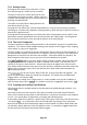
Two types of limits are available, Lines and Patterns. Up to two limits can be displayed, Limit 1
in red and Limit 2 in blue.
A Line is a simple horizontal line (single amplitude level) that can be set to any value.
A Pattern can have multiple levels and can include vertical steps and angled lines. Patterns are
contained within files that are lists of up to 100 frequency/amplitude points. When a file is used
by the instrument, linear interpolation is employed between the points.
Lines or patterns may be used as simple visual aids to determine whether a signal is within a
specific level range, or they may be used in conjunction with the Limits Comparator to create an
automatic action.