LCU-ONE CAN connected to MXL QM and EVO3 QM User Manual
LCU-ONE CAN connected to MXL QM and EVO3 QM User Manual Release 1.04 INDEX Chapter 1 – LCU–ONE ....................................................................................................... 2 1.1 – Part number ........................................................................................................................................ 2 Chapter 2 – LCU–ONE and Lambda probe mounting ..................................................... 3 Chapter 3 – Connection to MXL – EVO3 QM ..........
LCU-ONE CAN connected to MXL QM and EVO3 QM User Manual Release 1.04 0 Chapter 1 – LCU–ONE LCU-ONE is a lambda controller unit for the wide band BOSCH LSU 4.9 Lambda probe; it fits petrol (2 and 4 strokes), diesel and methane engines as well as alcohol based fuel engines.
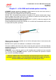
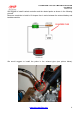
LCU-ONE CAN connected to MXL QM and EVO3 QM User Manual Release 1.04 1 Chapter 2 – LCU–ONE and Lambda probe mounting LCU-ONE controller should be installed in a flat location and far from heat sources; it should be mounted steady using the suited bracket. The wiring has to be arranged so to be far from heat sources. BOSCH LSU 4.9 lambda probe should be installed on the vehicle exhaust pipe using a specific adaptor that comes with the kit and should be welded on the same pipe.
LCU-ONE CAN connected to MXL QM and EVO3 QM User Manual Release 1.04 We suggest to install Lambda controller and the related probe as shown in the following pictures. Moreover we advise to install a 10 Ampere fuse in series between the external battery and lambda controller. We would suggest to install the probe in the exhaust pipe (see picture below): www.aim-sportline.
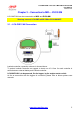
LCU-ONE CAN connected to MXL QM and EVO3 QM User Manual Release 1.04 2 Chapter 3 – Connection to MXL – EVO3 QM LCU-ONE CAN can be connected to all MXL and EVO3 QM. Warning: connect LCU-ONE to MXL QM or EVO3 QM OFF. 9 3.1 – LCU-ONE CAN Connection Lambda controller connection scheme is showed above. To protect Lambda Controller we suggest to insert one 10 A fuse for each controller in series between external battery and Lambda controller.
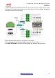
LCU-ONE CAN connected to MXL QM and EVO3 QM User Manual Release 1.04 In case more than one Lambda Controller are to be connected, for a better engine control (one probe for each engine bank or even one probe for each cylinder), peripherals connection scheme is the following: Each Lambda controller has to be connected to the battery. We would suggest to protect each Lambda controller with a 10 A fuse. When MXL/EVO3 QM is switched off all peripherals are automatically switched off. www.aim-sportline.
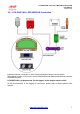
LCU-ONE CAN connected to MXL QM and EVO3 QM User Manual Release 1.04 13 3.2 – LCU-ONE CAN + GPS MODULE Connection Lambda controller connection to other CAN peripherals scheme is shown above. We suggest to insert a 10 A fuse in series between External Battery and Lambda controller to protect the latter. LCU-ONE CAN is to be powered, like the logger, by the engine master switch. As far as connection to the loggers is concerned, please refer to those systems user manual. www.aim-sportline.
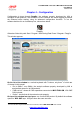
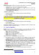
LCU-ONE CAN connected to MXL QM and EVO3 QM User Manual Release 1.04 3 Chapter 4 – Configuration Configuration is done through DragOn, the software properly developed by AIM to configure its QM products. This software is rich of features: we would suggest to practice the software before starting, using its advanced configuration functions. To run the software double click on its desktop icon, shown here below Otherwise follow this path: Start \ Program \ AIM Racing Data Power \ Dragster \ DragOn.
LCU-ONE CAN connected to MXL QM and EVO3 QM User Manual Release 1.04 On top of each layer is a photo of the logger the layer refers to. On its right are: • • • “Transmit” button: transmits the configuration to the logger; “Receive” button: reads the configuration of a logger connected to the PC and stores it in the configuration database; “Current configuration” table: shows all the most important information concerning the configuration user is working on.
LCU-ONE CAN connected to MXL QM and EVO3 QM User Manual Release 1.04 14 4.2 – Channels In order to correctly sample data transmitted by any additional sensor connected to the logger, each sensor needs to be connected to a proper analog channel and configured. To do so, it is necessary to set “Channels” layer. First of all activate it as shown here below: Central in this layer is channels table, whose columns are: Channel identifier: shows default channel identifier and cannot be modified.
LCU-ONE CAN connected to MXL QM and EVO3 QM User Manual Release 1.04 15 4.3 – System configuration System configuration is the most important operation to make in order to correctly sample data and show them on the logger display (if available). This layer layout depends on the logger to be configured: activate “System configuration layer” and fill in the window. 16 4.3.
LCU-ONE CAN connected to MXL QM and EVO3 QM User Manual Release 1.04 Channel for alarm and measure fields box: Each channel of the logger can be linked to one of the six lateral alarm leds of MXL QM. These channels can also be displayed on MXL QM display with the short name inserted in the related cell. Moreover it is possible to link alarm leds to the fields displayed, enabling the checkbox circled in the image here on the right.
LCU-ONE CAN connected to MXL QM and EVO3 QM User Manual Release 1.04 17 4.3.2 – EVO3 QM RPM box: If this info comes from a sensor installed on the vehicle, press “AIM sensor” button: ‘Multiply factor’ case enables: insert the proper multiply factor and RPM max value. If this info comes from the vehicle ECU, only insert RPM Max value. Gear sensor box: Engaged gear number can be sampled and shown or not (press “None” button).
LCU-ONE CAN connected to MXL QM and EVO3 QM User Manual Release 1.04 4 Chapter 5 – Configuration on MXL QM – EVO3 QM To use LCU-ONE CAN with MXL/EVO3 QM you need to configure it using DragOn software. Please refer to the installation manual for further information about the software. To configure Lambda Controller run the software and select the logger manager layer as explained before.
LCU-ONE CAN connected to MXL QM and EVO3 QM User Manual Release 1.04 The layer will be modified as shown below and as many additional layers as many lambda probes have been added appear. In case serial number has not been get, press “Get serial number from a connected expansion” button. Warning: this operation is necessary to be able to transmit the configuration to the logger. LCU-ONE layer is shown above. On top • Name of expansion configuration (6 characters max.) and serial number fields.
LCU-ONE CAN connected to MXL QM and EVO3 QM User Manual Release 1.04 In case a fuel not included in the database is being used and only in case its Stoichiometric value is known, press “Add custom value” button and the window shown below appears. Fill in the window with Multiplier value and related legend. Press “Add new item to list” and then “Save”.
LCU-ONE CAN connected to MXL QM and EVO3 QM User Manual Release 1.04 In case of an EVO3 QM, data visualisation is only possible if the logger is connected to a Formula Steering Wheel or to a MyChron3 Dash and displayed channels are set in that display configuration, as shown below.
LCU-ONE CAN connected to MXL QM and EVO3 QM User Manual Release 1.04 5 11 Chapter 6 – Data Visualisation on MXL QM/EVO3 QM 6.1 – Data Visualisation on MXL QM Lambda channels visualisation on MXL QM works exactly like the visualisation of any other MXL QM channel: switch from one page to the other is made using “MEM/View” button. Please refer to MXL QM user manual for further information. In the image below lambda value is 0.955 and assigned Short Name is LAM.
LCU-ONE CAN connected to MXL QM and EVO3 QM User Manual Release 1.04 6 Chapter 7 – Data Analysis with QMAn During data analysis, the presence of Lambda controller adds two channels to measures and laps toolbar (as shown below): Lambda: shows lambda value recorded during the session; Lambda _Temp: indicates the probe internal working temperature To better analyse carburetor values we would suggest to show XY diagram of Lambda probe with RPM values on abscissa axle and Lambda values on ordinate axle.
LCU-ONE CAN connected to MXL QM and EVO3 QM User Manual Release 1.04 7 Appendix – Technical drawings www.aim-sportline.
LCU-ONE CAN connected to MXL QM and EVO3 QM User Manual Release 1.04 www.aim-sportline.