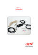
RPM Bridge USER MANUAL
RPM Bridge User manual Release 1.03 INTRODUCTION RPM Bridge belongs to the last generation of AIM systems for car installations. ECU Bridge samples but does not record RPM values coming from the vehicle. Data can be visualized connecting RPM Bridge to SmartyCam, the on-board camera or to an AIM dash (MyChron3 Dash, TG Dash, Formula Steering Wheel).
RPM Bridge User manual Release 1.03 INDEX Chapter 1 – Kit and part numbers ........................................................................................ 3 Chapter 2 – RPM Bridge characteristics.............................................................................. 4 Chapter 3 – Installation and powering ................................................................................. 5 3.1 – How to receive the RPM signal ....................................................................
RPM Bridge User manual Release 1.03 0 Chapter 1 – Kit and part numbers RPM bridge kit includes: • • RPM Bridge (4-50V and 150-450V)(1) USB programming cable (2) RPM Bridge part number is: X90BGRPMBM www.aim-sportline.
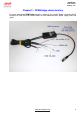
RPM Bridge User manual Release 1.03 1 Chapter 2 – RPM Bridge characteristics As shown here below RPM Bridge features a central 3 pins female Binder connector for PC interface via USB and three lateral cables for CAN communication, power supply and RPM signal. www.aim-sportline.
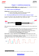
RPM Bridge User manual Release 1.03 2 Chapter 3 – Installation and powering Please ensure that RPM Bridge and its expansions are not in contact with heat or electromagnetic interference sources (like spark plugs and coil). 6 3.1 – How to receive the RPM signal RPM Bridge can receive the RPM signal in two ways: • • 9 from the ECU through a square wave signal (from 4 to 50V); from the coil low voltage input (from 150 to 450V). 3.1.
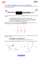
RPM Bridge User manual Release 1.03 10 3.1.2 – Sampling the RPM signal from the coil: low voltage RPM input If the vehicle is not equipped with an ECU, RPM signal can be taken directly from the low tension control of the coil.
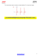
RPM Bridge User manual Release 1.03 The scheme below shows the voltage in the point labelled “1” in the previous images. It is reminded that RPM Bridge white cable, labelled “RPM 150-450 V” is to be connected to the RPM trigger wiring indicated by digit 1 in the previous schemes. www.aim-sportline.
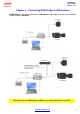
RPM Bridge User manual Release 1.03 3 Chapter 4 – Connecting RPM Bridge to AIM systems RPM Bridge can be connected directly to SmartyCam (top image) or to AIM dashes (bottom image) through a DataHub. Warning: connect RPM Bridge to AIM devices when both devices are OFF. www.aim-sportline.
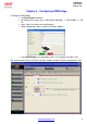
RPM Bridge User manual Release 1.03 4 Chapter 5 – Configuring RPM Bridge To configure RPM Bridge: • • • • run Race Studio 2 software, go through these steps: press “AIM System Manager” >> ”SMC Bridge” >> “Go to”; press “New” to create a new configuration; “New configuration” panel, shown here below, appears. • select RPM Bridge in the drop down menu, fill in the panel and press OK. The system comes back to “System manager” window. Enable “System Configuration” layer. www.aim-sportline.
RPM Bridge User manual Release 1.03 In case an AIM Display is available it needs configuration: activate “Display” layer and select the right display. Refer to Race Studio Configuration user manual to know how to configure each display. 7 5.1 – How to transmit the configuration To transmit the configuration the logger has to be switched on and connected to the PC USB port through the proper cable.
RPM Bridge User manual Release 1.03 Appendix – Technical drawing Firma / Sign Contr. da / Ckd. by CAN+ GND +Vb CAN+Vbatt 1 2 3 4 5 5 pins Binder 712 female connector pinout Solder termination view 4 5 pins Binder 712 female connector 3 5 1 2 Red cable +Vb ext Black cable GND RPM Bridge Blue cable RPM 8-50V Red cable Vb out Max 0,1A Black cable GND Data / date RPM Bridge pinout White cable RPM 150-450V N.rev. / Rev. N.