
Owner manual


RPM Bridge
User manual
Release 1.03
www.aim-sportline.com
5
2
Chapter 3 – Installation and powering
Please ensure that RPM Bridge and its expansions are not in contact with heat or
electromagnetic interference sources (like spark plugs and coil).
6
3.1 – How to receive the RPM signal
RPM Bridge can receive the RPM signal in two ways:
• from the ECU through a square wave signal (from 4 to 50V);
• from the coil low voltage input (from 150 to 450V).
9
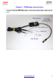
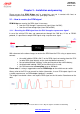
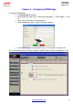
3.1.1 – Receiving the RPM signal from the ECU through a square wave signal
In case the vehicle ECU does not communicate through the CAN bus, K line or RS232
protocol, it is possible to sample RPM signal using a square wave signal.
With reference to the above image, to receive the RPM from the ECU using a square wave,
connect:
• the cable labelled “RPM 8-50 V” to the RPM signal out coming from the ECU
(or take RPM signal directly on the stock dashboard connector
1
);
• the red cable labelled “V battery” to the positive pole of the vehicle battery;
• the black cable labelled “GND” to the vehicle chassis earth;
• the CAN connector to SmartyCam or to an AIM dash.
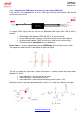
Please note: it is always suggested to connect RPM Bridge to the vehicle master switch.
Always refer to the ECU user manual for further information. In case ECU output signal is not
a steady square wave, an RPM adaptor (optional) is needed.
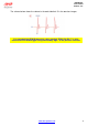
The images here below show a not-square RPM signal on the left and a filtered one on the
right.
1
RPM signal is often used to power stock dashes. This is why the signal is available on that wiring.