Plug&Play kit Yamaha R1 2004/2005/2006 – R6 2004/2005 User manual
MXL Plug&Play kit for Yamaha R1 2004/2005/2006 – R6 2004/2005/ User manual Release 1.01 INDEX Introduction ........................................................................................................................ 3 Chapter 1 – Plug&Play kit composition ........................................................................... 4 1.1 – Part Numbers ......................................................................................................................................
MXL Plug&Play kit for Yamaha R1 2004/2005/2006 – R6 2004/2005/ User manual Release 1.01 Presentation AIM: world leader in data acquisition for racing applications. Established in 1976, AIM is today a world leader producer of high performances instruments for racing applications: dashes, loggers, digital displays, lap timers.
MXL Plug&Play kit for Yamaha R1 2004/2005/2006 – R6 2004/2005/ User manual Release 1.
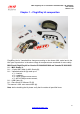
MXL Plug&Play kit for Yamaha R1 2004/2005/2006 – R6 2004/2005/ User manual Release 1.01 1 Chapter 1 – Plug&Play kit composition Plug&Play kits for Yamaha bikes changes according to the chosen MXL model and to the bike year of production. In the above image kit components are numbered for more clarity. MXL Strada Plug&Play kit for Yamaha R1 2004/2005/2006 and Yamaha R6 2004/2005: N.1 – MXL Strada (1); N.1 – 12 pins AMP cable for MXL Strada (2); N.
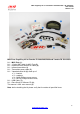
MXL Plug&Play kit for Yamaha R1 2004/2005/2006 – R6 2004/2005/ User manual Release 1.01 MXL Pista Plug&Play kit for Yamaha R1 2004/2005/2006 and Yamaha R6 2004/2005: N.1 – MXL Pista (1); N.1 – 12 pins AMP cable for MXL Pista (2); N.1 – Infrared receiver with 90 cm cable (3); N.1 – Infrared transmitter (4); N.1 – Transmitter power cable (5); N.1 – Yamaha bracket kit (6) made up of: n°1 – bracket; n°3 – washers; n°4 – M4*8 Phillips recess screws; n°3 – M5*18 Phillips recess screws; N.1 – USB Cable (7); N.
MXL Plug&Play kit for Yamaha R1 2004/2005/2006 – R6 2004/2005/ User manual Release 1.01 10 1.1 – Part Numbers MXL Strada Plug&Play kit for Yamaha R1 04/05/06: part number X16MXLSYR1407; MXL Strada Plug&Play kit for Yamaha R6 04/05: part number X16MXLSYR6450; MXL Pista Plug&Play kit for Yamaha R1 04/05/06: part number X16MXLCYR1407; MXL Pista Plug&Play kit for Yamaha R6 04/05: part number X16MXLCYR6450.
MXL Plug&Play kit for Yamaha R1 2004/2005/2006 – R6 2004/2005/ User manual Release 1.01 2 Chapter 2 – Plug&Play kit installation MXL Plug&Play kit for Yamaha R1/R6 has been expressly designed to guarantee maximum installation easiness. Please note: this kit has been expressly tested to guarantee total compatibility with a stock bike completely corresponding to the one sold by the manufacturer. The only compatible variation is the original YEK (Yamaha Engineering Corporation) kit.
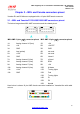
MXL Plug&Play kit for Yamaha R1 2004/2005/2006 – R6 2004/2005/ User manual Release 1.01 3 Chapter 3 – MXL and Yamaha connectors pinout Yamaha R1 and R6 bikes are equipped with a 16 pins AMP female connector. 8 3.1 – MXL and Yamaha R1 2004/05/2006 AMP connectors pinout The below image shows MXL AMP connectors and the related pinout.
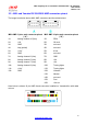
MXL Plug&Play kit for Yamaha R1 2004/2005/2006 – R6 2004/2005/ User manual Release 1.01 11 3.2 – MXL and Yamaha R6 2004/2005 AMP connectors pinout The image here below shows MXL AMP connectors and the related pinout.
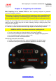
MXL Plug&Play kit for Yamaha R1 2004/2005/2006 – R6 2004/2005/ User manual Release 1.01 4 Chapter 4 – First start up and working mode MXL Plug&Play kit for Yamaha R1/R6 can be installed on stock bikes and on bikes equipped with original YEC (Yamaha Engineering Corporation) kit. Once the bike powered on, MXL automatically recognizes and shows on the display the kind of ECU installed.
MXL Plug&Play kit for Yamaha R1 2004/2005/2006 – R6 2004/2005/ User manual Release 1.
MXL Plug&Play kit for Yamaha R1 2004/2005/2006 – R6 2004/2005/ User manual Release 1.01 14 4.1.1 – Error codes in “Running mode” Yamaha bikes have a diagnostic feature that shows error codes. Here below are shown “Running Mode” error codes and the related meaning.
MXL Plug&Play kit for Yamaha R1 2004/2005/2006 – R6 2004/2005/ User manual Release 1.01 12 4.2 – Setting mode “Setting mode” allows to modify some ECU map settings. They changes depending on if it’s a stock ECU or an YEK kit. Powering on MXL it starts in “Running Mode”: press “MENU/<<” and “VIEW/QUIT” at a time to enter setting mode. The display shows “DIAG SETUP” message as here below. Confirm pressing “OK/MEM”. The display shows settable parameters in different pages.
MXL Plug&Play kit for Yamaha R1 2004/2005/2006 – R6 2004/2005/ User manual Release 1.01 15 4.2.2 – Setting mode with YEC ECU kit In case of a bike equipped with ECU YEC kit it is possible to modify both injection and ignition parameters. It is also always possible to come back to the default configuration. As shown on the injection map, it is possible to have richer or leaner air/fuel mixtures in nine different points of the map. In the below table characteristics of each point of the map are explained.
MXL Plug&Play kit for Yamaha R1 2004/2005/2006 – R6 2004/2005/ User manual Release 1.01 Warning: value selected in point “4” of the map (TPS>90 RPM<9.000) is applied in points 5,6,7,8 and 9 too. In these last pages the shown value is to be added to the one selected in point “4” of the map. Ex.: point “4” shows value 10%: the mixture is 10% richer in this point; point “5” shows value 3%: the mixture is 10+3=13% richer in this point. Ignition map is divided in 4 parts.
MXL Plug&Play kit for Yamaha R1 2004/2005/2006 – R6 2004/2005/ User manual Release 1.01 It is recommended to always refer to Yamaha YEC kit user manual to better take advantage from this fonctionality. ECU kit offers two other possibilities to modify parameters. Page INJN COR TO SPEED Description Value Modifies the quantity if 20 correction possibilities (+10/injected mixture according 10); to the vehicle speed.
MXL Plug&Play kit for Yamaha R1 2004/2005/2006 – R6 2004/2005/ User manual Release 1.01 5 4.3 – Diagnostic mode It allows to monitor the behaviour of sensors and signals out coming from the ECU. It is possible to switch from Running mode to diagnostic mode when the engine is off. To enter Diagnostic Mode from Running Mode press first “MENU/<<” and “VIEW/QUIT” at one time and then “MENU/<<” e “>>”.Diagnostic mode will show information concerning different sensors in different pages.
MXL Plug&Play kit for Yamaha R1 2004/2005/2006 – R6 2004/2005/ User manual Release 1.01 EXUP SUBTHROTTLE EXUP open angle When engine-off switch is selected and de-selected secondary throttle position changes from totally open to totally close.. ERRCODEEEPROM Cylinder number in (STOCK only) case of ECU EEPROM error. ERRHAPPENED (STOCK Shows the sequence only) of detected errors. ERRHAPPENEDCLR Shows the number of (Stock only) detected errors. Can be reset moving the engine switch from OFF to ON.
MXL Plug&Play kit for Yamaha R1 2004/2005/2006 – R6 2004/2005/ User manual Release 1.01 6 Chapter 5 – Calibration, gear calculation, configuration, data download and analysis MXL Strada/ Pista can show on the display the engaged gear. At first start up MXL starts gear calibration and shows “RUNNING GEAR CAL” on the display bottom string. Warning • For MXL to show engaged gear it is necessary to perform “Gear calibration procedure”. Refer to Race Studio configuration user manual to know how to do it.
MXL Plug&Play kit for Yamaha R1 2004/2005/2006 – R6 2004/2005/ User manual Release 1.01 7 Appendix – Wirings and pinout Rif. / Ref. Q.tà/Q.ty Progettato da / Designed by L.I. Firma / Signature Contr. da / Ckd.
MXL Plug&Play kit for Yamaha R1 2004/2005/2006 – R6 2004/2005/ User manual Release 1.01 N. rev. / Rev. N. Descrizione / Description Data / Date Firma / Signature Contr. da / Ckd. by Binder 719 connectors table Binder pin Cable colour Channel Connection Lenght 1 2 3 4 white black n.c. blue 8 6 Analogic input 5 Analogic GND 5 V Reference 1 1 2 3 4 white black n.c. blue 7 6 Analogic input 6 Analogic GND 5 V Reference 1 1 2 3 4 white black n.c.
MXL Plug&Play kit for Yamaha R1 2004/2005/2006 – R6 2004/2005/ User manual Release 1.01 N. rev. / Rev. N. Descrizione / Description Data / Date Firma / Signature Contr. da / Ckd. by Tabella connettori Binder 719 Pin Binder Colore cavo Canale Connessione Lunghezza 1 2 3 4 Bianco nero n.c. blu 8 6 Analog input 5 Analog GND 5 V reference 1 1 2 3 4 Bianco nero n.c. blu 7 6 Analog input 6 Analog GND 5 V reference 1 1 2 3 4 Bianco nero n.c.