CompM5s™ User manual
1 PRESENTATION Aimpoint® red dot sights are designed for the ”two eyes open” method which greatly enhances situational awareness and target acquisition. Thanks to the optical design the red dot follows the movement of the user’s eye while remaining fixed on target, eliminating any need for centering. 1.
Signature No forward optical signature from the dot beyond 10 meters Power source Battery type One AAA size 1.5 V Alkaline LR03 or Lithium FR03 Battery life3 More than 5 years of use at setting 7, more than 1 year at setting 8 and more than 10 years at NVD-setting (1-4). Size (L × W × H) Sight 83 mm × 40 mm × 49 mm 3.3 in × 1.6 in × 1.9 in Configuration 85 mm × 45 mm × 59 mm 3.4 in × 1.8 in × 2.3 in Weight Sight (incl. battery, excl. mount and lens covers) 165 g / 5.
Materials Sight and mount High strength aluminum, hard anodized, black to dark gray, non-glare finish Lens covers Thermoplastic elastomer, black, non-glare finish Environmental specification Temperature range (operation) -45 °C to +71 °C -49 °F to +160 °F Temperature range (storage) -51 °C to +71 °C -60 °F to +160 °F Water resistance 45 m / 147 ft.
1.2 Overview (configuration) 3 7 4 9 5 6 B 14 1 2 8 A 12 11 C 10 13 Fig.
2 OPERATION WARNING: Ensure the weapon is not loaded and the safety selector is in the ”safe” position before attempting to install, remove or perform maintenance. 2.1 Install battery a Remove the front lens cover (3) by pushing on the hinge in the direction away from the sight. b Untighten and remove the battery cap (1). If necessary, use the tool (14 B). c Insert battery (2) with the negative end (-) toward the battery cap (1) and the positive end (+) toward the sight as shown in Fig. 1.
2.2 Install Aimpoint® CompM5s on a weapon If the sight is equipped with the mount shown in Fig. 1, follow the described procedure. For installation with other mounts, see accompanying instruction. a Loosen the screw (12) using the tool (14 C), and clamp the locking bar (11) around the Picatinny rail.
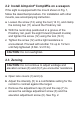
7 9 8 6 Fig. 2 Remove adjustment caps 6 Adjustment cap 7 Cap 8 Windage adjustment screw 9 Elevation adjustment screw d The adjustment cap (6) or the tool (14 A) must be used to turn the adjustment screws (8) and (9). Place the knobs on the adjustment cap (6) into the recesses on the adjustment screws (8) and (9). e Windage adjustments (see Fig. 3): • Turn windage adjustment screw (8) counterclockwise to move point of impact to the right.
NOTE: Each click of the adjustment screws (8) and (9) corresponds to a 10 mm movement of the point of impact at 100 m or .36 in at 100 yds. Fig. 3 Windage adjustments Fig. 4 Elevation adjustments g Confirm zeroing by firing at least three shots at a zeroing target. Check points of impact to confirm accuracy and repeat zeroing procedure if required. h After initial firing, ensure the sight is securely installed on the weapon.
3 EXTREME CONDITIONS • Extreme heat (moist or dry): no special procedures required. • Extreme cold: extreme cold might shorten battery life. The Intensity switch (5) can be more difficult to operate than at normal temperatures. • Salt air: no special procedures required. • Sea spray, water, mud and snow: ensure that the battery cap (1), the adjustment cap (6) and the cap (7) are tightened before exposing the sight to sea spray, mud, snow or before submerging the sight in water.
4 TROUBLESHOOTING The red dot does not appear or has disappeared Make sure contact surfaces in the battery compartment are clean and verify that a working battery (2) is installed correctly according to 2.1. If the intensity switch (5) is defective, notify local dealer/armourer. The sight is impossible to zero If an adjustment screw (8) or (9) is at its limit, check the alignment of mount and barrel.
Aimpoint AB Jägershillgatan 15 SE- 213 75 Malmö, Sweden Phone: +46 (0)40 671 50 20 Fax: +46 (0)40 21 92 38 e-mail: info@aimpoint.se Aimpoint Inc. 7309 Gateway Court Manassas, VA 20109, USA Phone: +1 703-263-9795 Fax: +1 703-263-9463 e-mail: info@aimpoint.com WWW.AIMPOINT.COM © 2018 Aimpoint AB.