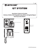
0311 A OI GT SYSTEM 6(59,&( 0$18$/ Apartment Intercom System Entrance Station (Unit Type)/Entrance Station (Integrated Type)/ Security Guard Station Entrance Station (Unit type) 3 E F D A B C 2 M P 7 W 9 S U V 8 T Q R O G N I 6 K L 5 H J 4 Z 1 X Y Entrance Station (Integrated type) 0 O N 9 Z S I L V T U W K 8 E 6 M P J G H 7 Q R Security guard station 3 D A B 5 F 2 4 C 1 X Y 0 OPERATION MANUAL
PRECAUTIONS General Prohibitions Prohibition to Dismantle the Unit Prohibition on Subjecting the Unit to Water General Precautions WARNING (Negligence could result in death or serious injury.) 1. Do not dismantle or alter the unit. Fire or electric shock could result. 2. Do not connect non-specified power sources to the +, - terminals. Also, do not install two power supplies in parallel to a single input. Fire, damage, or system malfunction could result. 3.
Table of Contents 1 NAMES Entrance Station (Unit type) ..............................................................................................................................4 Entrance Station (Integrated type) .................................................................................................................5 Security guard station..........................................................................................................................................
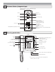
1 NAMES 1-1 Entrance Station (Unit type) Name scrolling module GT-NS-V (VIGIK-compatible) GT-NS Camera module GT-VA Display Back search button (or move the cursor to the left) Forward search button (or move the cursor to the right) Camera Illuminator LED Call button (or set and move forward) Speech module Cancel button (or set and return) GT-DA-L (guidance-enabled type) GT-DA 3 F D A E P 7 W 9 S U V 8 T Q R O M N I G K L 6 H J 5 In Use LED (orange) Door call-in indicator (G
1-2 Entrance Station (Integrated type) GT-DMV (Guidance-enabled + VIGIK-linked type) GT-DM (Guidance-enabled type) Microphone Camera Illuminator LED Speaker In Use LED (orange) Display Back search button (or move cursor to the left) Forward search button (or move cursor to the right) 10 key (0 to 9, , #) Cancel button (or set and return) Call button (or set and move forward) Sensor (If the sensor detects an object, the display will be illuminated.
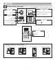
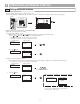
2 OPERATIONS (ENTRANCE STATION) 2-1 Calling residential stations ● Calling with the switch module Press the call button for the residence that you want to call. The door call-in indicator will light up and you will hear a call tone. Audio guidance will be heard depending on the settings. GT-SW GT-DA-L ● Calling with the name scrolling module or GT-DMV/GT-DM. Display the residential station to be called.
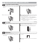
(3) Display by using letters to search 1 In the standby mode, press [ ] on the 10 key. GT-NS-V/GT-NS GT-DMV/GT-DM WELCOME WELCOME 2 When "ENTER A LETTER" displays, use the 10 key to enter letters. ENTER A LETTER 7 S S S 7 Q R P :CALL 7 Q R P Q R P P 7 S ENTER A LETTER Q R ... S :CANCEL Resident name (ex. "SMITH") 3 The room number and name for the resident whose initial corresponds to the entered letter will display. • Depending on the settings, the resident name may only display.
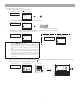
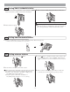
5 When the other person answers, communication starts and the talk indicator lights up. Audio guidance will be heard depending on the settings. GT-DMV/GT-DM GT-NS-V/GT-NS IN COMMUNICATION GT-DA-L IN COMMUNICATION ROOM NO. 101 SMITH :CANCEL 6 When the door is released, the door release indicator lights up. Audio guidance will be heard depending on the settings. GT-NS-V/GT-NS GT-DMV/GT-DM DOOR OPEN GT-DA-L IN COMMUNICATION ROOM NO.
3 3-1 1 OPERATIONS (SECURITY GUARD STATION) Calling from an entrance station When the call is from an entrance station, the call tone will ring for approximately 10 seconds and the entrance station number will be displayed. 3 When you are done talking, hang up the handset to end the call. • Communication ends automatically after approximately 3 minutes.
3-4 1 Calling from a residential station When a call is received from a residential station, a call tone will sound for approximately 10 seconds and the room number and resident name will be displayed. 3 When you are done talking, hang up the handset to end the call. 1 2 5 T 8 B C D H J I S K L U 3 E F 6 W R M P 7 A G 4 Q 9 V N O Y Z X 0 NOTES: If a call is not responded to, a record is kept.
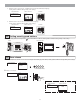
3-7 Calling residential stations Lift the handset, display the name and press the button. Making a call by entering the room number Enter the room number with the 10 key. AIPHONE 1 S K C T 3 6 9 L E 8 U V X 0 F N O Y Z B W 5 M P J G 2 I R D A H 0 Room number (1 to 6 digits) 1 4 7 Q 1 101 SMITH Making a call by name scrolling Use the and buttons to search names by scrolling. AIPHONE AIPHONE 7 S S 7 Q R P 7 Q R P 7 Q R S ENTER A LETTER P 3.
Calling another security guard station Lift the handset, display the security guard station and press the 1 1 2 AIPHONE E F 5 6 K L N O 7S 8 R 9Z WX U V 0 7 Q R P 7 Q R P P P 7 Q R 7 ... S ENTER A LETTER Making a call by security guard station name scrolling Use the and buttons to search security guard station names by scrolling.
3-9 1 Missed call If a security guard station fails to respond to a call from a residential station, "MISSED CALLS" is displayed on the display. Press the button to display the room number and name of the residential station that made the call. MISSED CALLS 1 2 3 When the room number and name is displayed, press the button to erase the displayed record. Other records will not be deleted. 101 SMITH NOTES: 1. 2. The security guard station can hold up to 20 missed calls.
3-11 Emergency call 1 When an emergency alarm switch is locked (or when a wire disconnection occurs), an alarm sounds at the security guard station and "EMERGENCY" and the room number are displayed alternately. Press the button to stop the alarm. 2 Lift the handset, check the name on the display and press the to communicate with the residential station. H 2 5 T 8 I R B K U C L 3 E 9 V N X 0 - 14 - F 6 W P 7 M 4 Q J 6. 1 G 5. 2 D 4.
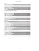
4 Setting list 4-1 Setting list The following settings are possible at an entrance station or security guard station. • The program menu varies according to the unit. × = These items are set when a unit is installed. When making changes, consult with an qualified installer. ○ = These items can be set according to the installation equipment and unit application. GT-DMV/GT-DM GT-NS-V/GT-NS, GT-DA-L/GT-DA, GT-VA Page no.
5 CHANGING SETTINGS (ENTRANCE STATION) 5-1 Setting method When changing settings, use the GT-NS-V/GT-NS or GT-DMV/GT-DM program mode. ● Program Mode 1 In the standby mode, enter the 4-digit ID code after entering [#] and [ ] on the 10 key. (Initial setting: 1111) GT-NS-V/GT-NS GT-DMV/GT-DM WELCOME WELCOME 1 1 1 1 ID code 2 The "RE-ENTER ID CODE" is displayed. Re-enter [ ] and the 4-digit ID code. RE-ENTER ID CODE ENTER ID CODE RE-ENTER ID CODE _ 1 The first menu item is displayed.
5-2 Display language selection ● Start the program mode with the GT-NS-V/GT-NS or GT-DMV/GT-DM and select "SELECT LANGUAGE". Select English, French, German, Spanish, Dutch, or Italian.
5-4 Changing the ID code 1 Start the program mode and select "CHANGE ID CODE". GT-NS-V/GT-NS CHANGE ID CODE GT-DMV/GT-DM MENU SELECT LANGUAGE GUIDE LANGUAGE CHANGE ID CODE :ENTER The current ID code is displayed. Enter the new 4-digit ID code after entering [ ] on the 10 key. Current ID code CHANGE ID CODE ENTER ID CODE *1111 0 1 3 B E New ID code (Ex.: "0123") :ENTER 3 Press the D 2 A * + 4 DIGITS F CHANGE ID CODE *1111 C 2 button to return to the menu.
5-6 Changing resident information Up to 500 resident information entries can be registered. ● Programming with the GT-NS-V/GT-NS or GT-DMV/GT-DM 1 Start the program mode and select "RESIDENT INFO.". GT-NS-V/GT-NS RESIDENT INFO. GT-DMV/GT-DM MENU ACCESS CODE RESIDENT INFO. SET TIMER :ENTER 2 Enter the room number that is to be newly registered or have data changed using [0] to [9] on the 10 key, and then press the can have up to 6 digits. ROOM # RESIDENT INFO. ROOM # 1 MAX 6 DIGITS :NEXT 3 button.
5-7 Setting messages and the standby screen ● GT-DMV/GT-DM: Start the program mode and select "STANDBY SCREEN". Select from the following in the standby screen display. • Greeting message • Operation message • Original picture GT-DMV/GT-DM MENU STANDBY SCREEN BRIGHTNESS SORT SETTING :ENTER STANDBY SCREEN GREETING OPERATION PICTURE :ENTER * Uploading an original picture These items are set when a unit is installed. When making changes, consult with an qualified installer.
5-8 Adjusting screen brightness Screen brightness can only be adjusted with the GT-DMV/GT-DM. ● Start the program mode and select "BRIGHTNESS". Set a digit from 0 to 9. 0 = Dark 9 = Bright. GT-DMV/GT-DM MENU STANDBY SCREEN BRIGHTNESS SORT SETTING :ENTER BRIGHTNESS P 7 S 4 Q R DARK 0----9 BRIGHT Next menu item 0-9 :ENTER 5-9 Setting the search order Select either name order or room number order for searching at the entrance station.
6 CHANGING SETTINGS (SECURITY GUARD STATION) 6-1 Setting method When changing settings, use the program mode. ● Program Mode 1 In the standby mode, enter the 4-digit ID code after entering [#] and [ ] on the 10 key. (Initial setting: 1111) AIPHONE 1 1 1 1 ID code 2 The "RE-ENTER ID CODE" is displayed. Re-enter [ ] and the 4-digit ID code. RE-ENTER ID CODE 1 1 1 1 ID code 3 The first menu item is displayed. Use the and SELECT LANGUAGE 4 buttons to select the desired menu item.
6-4 Changing resident information Up to 500 resident information entries can be registered. ● Programming with the GT-MK 1 Start the program mode and select "RESIDENT INFO". RESIDENT INFO. 2 Enter the room number that is to be newly registered or have data changed using [0] to [9] on the 10 key, and then press the numbers can have up to 6 digits. ROOM # 1 0 button. Room 1 Room number (1 to 6 digits) 3 The room number is displayed.
7 TECHNICAL PRECAUTIONS TECHNICAL PRECAUTIONS • Operating temperature: Entrance station: -10 °C to +60 °C (+14 °F to +140 °F) Security guard station: 0 °C to +40 °C (+32 °F to +104 °F) • Mounting location: Do not install the entrance station in a place where there would be a bright light behind a visitor (or where there would be a bright background) or in a place where the camera lens would be directly exposed to sunlight or a bright light.
Aiphone warrants that its products have no material or workmanship defects under normal use conditions for two years after delivery to the end user. Aiphone will perform repair or replacement free of charge if the product is defective and the warranty applies to the defect. Aiphone reserves unto itself the sole right to make the final decision whether there is a defect in materials and/or workmanship and whether or not the product is under warranty.