INSTALLATION MANUAL VOICE SECURITY SYSTEM AI-900 Be sure to leave system installations, adjustments, and data settings to the dealer from whom you have purchased. Please follow the instructions in this manual to obtain the optimum results from this unit. We also recommend that you keep this manual handy for future reference.
TABLE OF CONTENTS 1. SAFETY PRECAUTIONS ..................................................................................... 4 2. FCC REQUIREMENTS ......................................................................................... 6 3. INDUSTRIAL CANADA REQUIREMENTS .................................................... 7 4. GENERAL DESCRIPTION .................................................................................. 8 5. FEATURES ...............................................................
12. WIRING 12.1. Wiring from the Station or Outside Line .............................................................. 21 12.2. Supplied Connector Connection ......................................................................... 22 12.3. AI-900MS Master Station Interface Card Connection 12.3.1. Master Station and AI-900MS connection .............................................. 23 12.3.2. External recording device and AI-900MS connection ............................ 25 12.4.
1. SAFETY PRECAUTIONS • Be sure to read the instructions in this section carefully before use. • Make sure to observe the instructions in this manual as the conventions of safety symbols and messages regarded as very important precautions are included. • We also recommend you keep this instruction manual handy for future reference.
• Do not touch the power cord during thunder and lightning, as this may result in electric shock. • Do not connect any power supply other than specified to the AI-900MF's DC power input terminals. Doing so could result in fire or damage to the unit. [Applicable to the exchange] • Do not block the ventilation slots in the unit's cover. Doing so may cause heat to build up inside the unit and result in fire.
2. FCC REQUIREMENTS (1) The AI-900 complies with FCC Rules, Part 68. On this equipment is a label which contains, among other information, the FCC Part 68 registration number. (2) The ringer equivalence number (REN) is used to determine the quality of devices which may be connected to the telephone line. Excessive RENs on the telephone line may result in the devices not ringing in response to an incoming call. In most, but not all areas, the sum of RENs should not exceed five (5.0).
3. INDUSTRY CANADA REQUIREMENTS (1) ''NOTICE: This equipment meets the applicable Industry Canada Terminal Equipment Technical Specifications. This is confirmed by the registration number. The abbreviation, IC, before the registration number signifies that registration was performed based on a Declaration of Conformity indicating that Industry Canada technical specifications were met. It does not imply that Industry Canada approved the equipment.
4. GENERAL DESCRIPTION The AI-900 Security System is a voice communication system that permits calls to be quickly and easily made - even in emergency situations - with the touch of single button. The system can record conversations, and features external equipment sync output and operation log output. These features combine to make the AI-900 an ideal system for voice security applications. 5. FEATURES • Modular construction facilitates installation, maintenance, and system expansion.
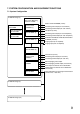
7. SYSTEM CONFIGURATION AND EQUIPMENT FUNCTIONS 7.1.
7.2. Equipment Functions • AI-900MF Main Frame The AI-900MF accommodates the following cards: Up to 2 AI-900MS or AI-900AL Cards (both cards may be mixed), up to 4 AI-900RS Cards, 1 AI-900CO Card, 1 AI-900AF Card, and 1 AI-900TI Card. The Main Frame has 2 RS-232C ports; one for programming and the other for operation log output. • AI-900MS Master Station Interface Card The AI-900MS is used for master station connection.
8. AI-900MF MAIN FRAME NOMENCLATURE AND FUNCTIONS 1 2 3 12 10 4 11 5 1. AC Input Connectors Connect to the AC output terminal of the AI-PU200 power transformer unit. (See p. 39.) 2. 24 V DC Input Connector Connects to a battery (24 V DC). (See p. 39.) 3. Power Switch Power is switched on (I) and off (O) with each depression of this switch. 4. Backup Battery Socket Insert the CR2032 data backup battery into this socket. (See p. 19.) 5.
9. INSTALLATION AND CONNECTION PROCEDURES (1) System Design Exchange/Station Configuration, Wiring Schedule and Station Numbering Schedule (2) Equipment Installation Installing the AI-900MF Main Frame in an Equipment Rack or on a Wall (See p. 13.) Installing the AI-PU200 Power Transformer in an Equipment Rack or on a Wall (See p. 15.) Installing the Substation (See p. 17.) Installing the Master Station (See p. 18.
10. EQUIPMENT INSTALLATION 10.1. AI-900MF Main Frame 10.1.1. Rack mounting Step 1. Attach the supplied rack mounting brackets to the frame. Machine screw M4x10 (6 places) Mounting bracket Step 2. Mount the frame to an equipment rack.
10.1.2. Wall mounting (Optional AI-YC303 Wall Mounting Frame is required.) Step 1. Mount the AI-YC303 bracket to the wall. 55.2 30 78 78 78 Knockout (for wiring) 141.3 440.6 200 391.4 Wood screw 5.1x38 290 Mounting dimensions Step 2. Remove the AI-900MF's front panel, then mount the AI-900MF on the AI-YC303.
10.2. AI-PU200 Power Transformer Unit 10.2.1. Rack mounting Step 1. Remove the 4 mounting screws, and attach the supplied wall mounting brackets to the transformer unit using the removed screws. Wall mounting bracket Mounting screw Step 2. Attach the AI-PU200 to the AI-PN100B Rack Mount Panel. AI-PN100B Machine screw (M3 x 8) AI-PU200 Step 3. Mount the AI-PN100B in an equipment rack. Fiber washer Note Perform terminal wiring before mounting.
10.2.2. Wall mounting Step 1. Remove the 4 mounting screws, and attach the supplied wall mounting brackets to the transformer using the removed screws. Wall mounting bracket Mounting screw Step 2. Mount the transformer to the wall using the supplied wood screws. 140 Unit: mm 25 115 Wood screw 3.
10.3. AI-RS150, AI-RS160, AI-RS170 and AI-RS180 Substations Mount the substation to an electrical box mounted in the wall. 2-gang electrical box (deep) and adapter ring AI-RS150/-RS160/-RS170/-RS180 Oval head screw UNC No.6x18 Dimensional diagram 46 120 37 120 18.2 83.5 Unit: mm 3 *1 52.5 *2 * * 1 2 2 (AI-RS150) 43.
10.4. Master Station 10.4.1. Desk-top mounting Connect the supplied modular-plug cord. 10.4.2. Wall mounting Pull out, rotate, and reset the cradle hook, then mount the station on the wall using the supplied wall mounting frame. Remove the cradle hook.
11. AI-900MF CARD INSTALLATION 11.1. Backup Battery Installation Caution All cards contain many CMOS ICs which are easily damaged by static electricity. Do not touch circuit components. • Insert the backup battery into the Main Frame mother board before installing any cards. CR2032 BATT1 AI-900MF Battery replacement As the battery life is rated at about 4 years, replace it with a new one every 4 years. Follow the replacement procedure below. Step 1. Switch the Main Frame (AI-900MF) power off. Step 2.
11.2. Card Installation Step 1. Remove each card from its static-protective bag, and install it in its designated position in the Main Frame. • For the AI-900TI, perform exchange number setting BEFORE installation. Refer to p. 38 "Exchange Number Setting." Step 2. After installing all cards, secure them using the supplied fixing bracket. The top and side panels are omitted to show the hidden parts.
12. WIRING 12.1. Wiring from the Station or Outside Line Step 1. Remove the main frame's bottom panel as shown below. Step 2. Connect stations or outside lines to their respective cards as shown below.
12.2. Supplied Connector Connection Use the supplied connectors for exchange connections as follows. Step 1. Insert a cable into the connector and tighten the screw. Step 2. After cable connection is completed, press the connector onto the circuit board's connector.
12.3. AI-900MS Master Station Interface Card Connection 12.3.1. Master Station and AI-900MS connection • The AI-900MS can be interfaced with up to 2 AI-MS900 master stations. • Because up to 2 AI-900MS cards can be mounted in the AI-900MF Main Frame, up to four master stations can be connected per frame. • A station address must be assigned to each connected AI-MS900 station. Set the station address at each AI-MS900 station after switching ON the power. [Station Address Setting] Step 1.
[Connection] Use 2 twisted pair cables with a modular jack fitted at each one end to connect the AI-MS900 to the AI-900MS. Refer to the following table for the maximum recommended cable length between the two. Cable type AWG24 (0.52 mm) Distance 0.9 km AWG22 (0.65 mm) 1.5 km AWG20 (0.82 mm) 2.3 km Connect as shown below.
12.3.2. External recording device and AI-900MS connection An external recording device can be connected to each master station line. [Connection] To connect the external recording device, use a twisted pair cable for voice output, and a twisted pair cable for control output. The voice output is 0 dB* and of unbalanced type. The control output is an open collector output 20 mA, 24 V DC max. Connect as shown below.
12.4. AI-MS900 Master Station Connection and Adjustment 12.4.1. External speaker connection Follow the procedures below when connecting an external speaker (8Ω). Step 1. Remove the AI-MS900's rear terminal cover and set the internal slide switch to the [EXT. SP] position. Internal/External speaker selection switch Terminal cover EXT.SP terminal Microphone sensitivity control Internal speaker volume control Step 2. Connect the speaker cable to EXT.SP terminal. Speaker cable Step 3.
12.5. AI-900AL Telephone Interface Card Connection 12.5.1. Telephone and AI-900AL connection The AI-900AL can be interfaced with up to 2 commercial telephone sets. Use the telephone which complies with the FCC Regulation Part 68. [Connection] To connect the telephone set to the AI-900AL, use a twisted pair cable. The connector of the cable end going to the telephone needs to be the type that can be connected to the telephone connector.
[Setting telephone's talking volume levels] When the talking volume is low, set it using the switch SW101 (for Line 1) or SW201 (for Line 2) on the AI-900AL card as illustrated below.
12.5.2. External recording device and AI-900AL connection An external recording device can be connected to each telephone line. [Connection] To connect the external recording device, use a twisted pair cable for voice output, and a twisted pair cable for control output. The voice output is 0 dB* and of unbalanced type. The control output is an open collector output of 20 mA, 24 V DC max. Connect as shown below.
12.6. AI-900RS Substation Interface Card Connection 12.6.1. Substation and AI-900RS connection The AI-900RS can be interfaced with up to 16 substations. [Connection] Use a 2-core shield cable to connect the substation to the AI-900RS. Refer to the following table for the maximum recommended cable length between the two. Cable type AWG24 (0.52 mm) Distance 0.5 km AWG22 (0.65 mm) 0.8 km AWG20 (0.82 mm) 1.3 km Connect as shown below.
12.6.2.
12.7. AI-900CO Outside Line Interface Card Connection 12.7.1. Outside line and AI-900CO connection The AI-900CO can be interfaced with up to 2 outside lines. Using DTMF tone dialing, it is compatible with both loop and ground start systems. [Connection] Connect as shown below.
12.7.2. External recording device and AI-900CO connection An external recording device can be connected to each telephone line. [Connection] To connect the external recording device, use a twisted pair cable for voice output, and a twisted pair cable for control output. The voice output is 0 dB* and of unbalanced type. The control output is an open collector output o f 20 mA, 24 V DC max. Connect as shown below.
12.8. AI-900AF Audio Function Card Connection 12.8.1. Amplifier and AI-900AF connection Paging can be provided through connected external amplifiers using the AI-900AF. [Connection] To connect the amplifier to the AI-900AF, use a twisted pair cable for voice output, and a twisted pair cable for control output. The voice output is 0 dB* and of unbalanced type. The control output is an open collector output of 20 mA, 24 V DC max., and permits connection of up to 16 channels. Connect as shown below.
12.8.2. External sound source and AI-900AF connection The External Sound Source Distribution function can be operated using the AI-900AF. [Connection] To connect external sound sources to the AI-900AF, use a twisted pair cable for voice input, and a twisted pair cable for control input (level-operated activation). The voice input is 0 dB* and of unbalanced type. The start input is a no-voltage make contact of 20 mA, 24 V DC max. Connect as shown below.
12.9. AI-900TI Tie-Line Interface Card Exchange Interconnection Up to 16 exchanges can be tie-line interconnected using the AI-900TI card. [Connection] To interconnect the exchanges, use 2 twisted pair cables for voice lines, and a 2-core shielded cable for data lines. A maximum of 4 voice lines can be connected. Refer to the following table for the maximum recommended length for each cable type between exchanges. (As to the cable connection, see the figure on the next page.) Cable type AWG24 (0.
Connect as shown below.
[Exchange Number Setting] When interconnecting the exchanges using the AI-900TI, assign the exchange number to each exchange with the SW1 switch located on the AI-900TI's circuit board. (Refer to the table below.) Exchange No. setting Initial status: Exchange No. 1 1 ON CN6 1 2 3 4 5 6 7 8 8 SW1 AI-900TI 38 Exchange No.
12.10. AI-900MF Main Frame and AI-PU200 Power Transformer Connection [Connection] Connect as shown below using 2 parallel pair cables. Use cables with a sufficient current capacity and a heavier gauge than AWG18. Two AI-PU200 units are required when using 3 or 4 AI-900RS cards. AI-900MF and power supply connection AI-900MF from AI-PU200 AC-IN AC-IN 1 2 from AI-PU200 AC-IN AC-IN 3 4 DC24V IN G1 FG 24 V DC OUTPUT 20V AC 2.5A OUTPUT 20V AC 2.5A 20V AC 2.
13. MAIN FRAME AND PC CONNECTION 13.1. Programming PC Connection 13.1.1. Direct connection by means of RS-232C Using the RS-232C cable, connect the programming PC to the AI-900MF Main Frame as shown below.
13.1.2. Connection via modem Connect as shown below.
13.2. Operation Log PC Connection 13.2.1. Direct connection by means of RS-232C Using the RS-232C cable, connect the operating log PC to the AI-900MF as shown below.
13.2.2. Connection via modem Connect as shown below. Connection via modem (Operation log PC) RS-232C cross cable AI-900MF 1 DCD 2 RXD 3 TXD 4 DTR 5 GND 6 DSR 7 RTS 8 CTS 9 RI Modem DCD RXD TXD DTR GND DSR RTS CTS RI 1 2 3 4 5 6 7 8 9 COM1 COM2 Modem RS-232C cross cable Front view Main Frame AI-900MF 13.3. System Programming Use the supplied PC software to perform such system programming as station number and function settings.
14. SPEECH AND FUNCTION TESTS Using installed equipment, perform both speech and function tests after system programming completion. 14.1. Speech Test (1) Calls from the substation • Call the Master Station (telephone) from each substation to check to be sure that a conversation is possible. Also, check to confirm that the master station (telephone) registered in system programming is correctly called.
15. SPECIFICATIONS [AI-900MF Main Frame] Power Source Current Consumption Speech Path Configuration Serial port Installation Method Other Connection Terminal Operating Temperature Finish Dimensions Weight 20 V AC, 24 V DC 5.
[AI-900AL Telephone Interface Card] Power Source Current Consumption Supply Power Number of Lines Conversation Recording Output Selectable Signal Type Monitoring Function Applicable Terminal Control Function Connection Terminal Weight 5 V DC, 15 V DC, 24 V DC (supplied from the main frame) 150 mA (5 V DC), 30 mA (15 V DC), 200 mA (24 V DC) 24 V DC, 80 mA 2 lines Audio signal: 0 dB*, unbalanced Control signal: Open collector output, withstand voltage: 24 V DC, control current: 20 mA DTMF signal Line loop
[AI-900CO Outside Line Interface Card] Power Source Current Consumption Number of Lines Conversation Recording Output Selectable Signal Type Signal Format Main Functions Connection Terminal Weight 5 V DC, 15 V DC, 24 V DC (supplied from the main frame) 300 mA (5 V DC), 50 mA (15 V DC), 50 mA (24 V DC) 2 lines Audio signal: 0 dB*, unbalanced Control signal: Open collector output, withstand voltage: 24 V DC, control current: 20 mA DTMF signal Loop start and Ground start compatible DTMF dial signal transmis
[AI-900TI Tie-Line Interface Card] Power Source Current Consumption Number of Audio Links Connection Format Transmitting System Input/Output Level Other Connection Terminal Weight 5 V DC, 15 V DC (supplied from the main frame) 100 mA (5 V DC), 50 mA (15 V DC) 4 links Multidrop system Data: RS-485 Voice: Base band Voice: 0 dB*, balanced Data: In compliance with RS-485 Standard Exchange number setting function Main frame connection side: DIN connector (64-pin, male) Tie-line interface side: 4-pin x 4 (Voice