NETWORK INTERCOM SYSTEM AN-8000 SERIES Quickstart Guide Thank you for purchasing AIPHONE's Network Intercom system. Please carefully follow the instructions in this manual to install and troubleshoot this system.
AN Quickstart Guide Topics Overview Section 1 Section 2 Section 3 Section 4 Section 5 Section 6 Appendix A Designing the System Equipment List Setting Up Stations Uploading and Testing Advanced: Call Forwarding Advanced: Paging Zones Advanced: Group Blocking Advanced: Integration Troubleshooting Web Interface Logs Setup a network the system will use to communicate Tell the software what hardware it will connect to Configure master stations and door stations Save and upload and verify desired functionalit
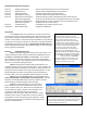
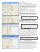
Section 2 Equipment List and Station Table The Equipment Registration tab of the General section is used to tell the software which equipment the system will use. Step 2.1 The Content section of the Equipment Registration tab must be filled out with the specified quantities of each type of AN equipment in the system so the software is aware of each part. Change each line in the Content section from 0 to the intended quantity and press enter and an Equipment No.
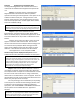
Section 3 Setting up Stations Step 3.1 Setting up Door Stations Door stations have a single call button that will Speed Dial a master when pressed. Switch to the Station (or IP Station) tab and for every door station select the Station No. from the Station selection area at the top. Under the Speed Dialing tab there is a Master Station No. field, enter the master station’s Station number that door station should speed dial.
Section 5: Advanced Step 5.1 Advanced: Call Forwarding To set up automatic transferring and multiple masters getting a call, each feature must be enabled in the Exchange’s Function Settings tab, or in Function Settings1 of an IP master and then specific assignments must be made in the called station’s Function Settings(2) tab. There are 4 ways to forward an incoming call. Call forwarding: This forwards the call immediately.
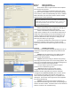
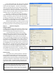
In the “Group blocking to” tab, each column represents a segment of the system and the rows beneath it determine access to the other segments. The rule is a checked box allows an interaction from the Group column to the object row, a blank box denies that interaction. The reverse is not necessarily true, so Group 1 may be able to dial Group 2, but Group 2 would not be able to dial them back unless there is a check box next to 1 under the Group 2 column.
Section 6: Troubleshooting The first step in troubleshooting an AN system is to operate it and find out what happens. If something unexpected or unintended happens then there are several features and tools available to find the cause of the problem, but the most important thing to do is to determine what happened and what was supposed to happen. Lights, sounds, the LCD display, the command line and web interface all give clues. This guide will first cover connecting, then calling, then communication.
Section 6.2 Configuration Testing The Web Interface A web browser like Internet Explorer or Firefox can be used to interact with the web interface of AN equipment. Initially the IP address is 192.168.1.1 (although it may have been changed in Unit Scan) and the default user name is AN8000 and the password is guest, both are case sensitive. Try the default user name and password, and then if that fails try the system name and password given in any previous upload attempt.
Section 6.3 Troubleshooting Calling Notice the “grayed out” 14 in the disabled Time-based call forwarding to: field. A partially disabled feature or a conflicting forward or transfer can cause very strange problems like the one described above. Also notice the NONE under Group Call, Call forwarding to, Absence Transfer to, and Group hunting to: fields. NONE indicates a station number was specified but then the station number was changed or deleted from the system.
Troubleshooting a Door Station Every time the Call button is pressed it should make some kind of noise and the light should do something. Pressing the Call button and watching the light and listening to the ring tone will help narrow down a problem. The web interface can also simultaneously check the Operation Status for what the device (and the master it is attempting to Speed dial) is doing. These are the most common events for the door: 1.
Appendix A: Web Interface Operation Log Definitions Operation Log entry definitions Normal entries: “Speech path connection” means the station is being brought out of “standby” mode and into “operating” mode. It will tell you the station it is attempting to reach on the LCD display or on the Operation Log. “Speech path disconnection” means the attempt to communicate is over and the station will return to its neutral “standby” state.
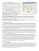
Network Map Example and Workspace Network Layout Content on this segment Network 1: Site Name ________ EX #’s ______ MI’s______ Subnet Mask: ___.___.___.___ IP Masters ____________ Gateway ___.___.___.___ IP Door #’s ____________ Network 2: Site Name ________ EX #’s ______ MI’s______ Subnet Mask: ___.___.___.___ IP Masters ____________ Gateway ___.___.___.___ IP Door #’s ____________ Network 3: Site Name ________ EX #’s ______ MI’s______ Subnet Mask: ___.___.___.___ IP Masters ____________ Gateway ___.___.
AN System Configuration Sheet Key: Station # numbers can be 2-6 digits and should not start with 7,8,9 or 0 to avoid Speed Dialing conflicts. Model # choices for Exchange Ports are AN-8000MS, AN-8010MS, AN-8011MS, AN-8020MS, AN-8031MS, or AN-8050DS. Name (optional) must be 8 characters or less. Speed Dial should specify which master a door calls. System Name: _____________ Password: __________ AN-8000EX # ___ IP Address: ____.____.____.____ AN-8000EX # ___ IP Address: ____.____.____.