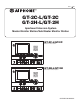
0311 A OI GT-2C-L/GT-2C 6(59,&( 0$18$/ GT-2H-L/GT-2H Apartment Intercom System Master Monitor Station/Sub Master Monitor Station GT-2C-L/GT-2C Master monitor station GT-2H-L/GT-2H Sub master monitor station OPERATION MANUAL
PRECAUTIONS General Prohibitions Prohibition to Dismantle the Unit Prohibition on Subjecting the Unit to Water General Precautions WARNING (Negligence could result in death or serious injury.) 1. High voltage is present internally. Do not open the case. Electric shock could result. 2. Do not dismantle or alter the unit. Fire or electric shock could result. 3. Do not connect non-specified power sources to the +, - terminals. Also, do not install two power supplies in parallel to a single input.
Table of Contents 1 NAMES Master monitor station (GT-2C-L/GT-2C) ....................................................................................................4 Sub master monitor station (GT-2H-L/GT-2H) ..........................................................................................4 2 VIEWING THE SCREEN (MASTER MONITOR STATION) ............................................................................5 3 OPERATING METHOD (MASTER MONITOR STATION) Turning off the screen display ............
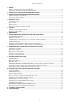
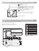
1 NAMES Master monitor station (GT-2C-L/GT-2C) Color LCD video monitor Screen brightness control (0∼10) Speaker Adjust the LCD screen brightness. Hearing aid T-mode compatibility symbol*1 (GT-2C-L only) MENU CALL MONITOR REC/PLAY button button button button Receive volume control (0∼10) ADJUST button ZOOM/WIDE button Adjust the receive volume during communication. At "0", no sound is output. PAN/TILT button Indicated with STWX button symbols.
2 VIEWING THE SCREEN (MASTER MONITOR STATION) CALLING ENTRANCE1 MAY/26 18:45 Displays during recording or playing :Recording :Play Door release operations are indicated. (This does not exactly correspond to the door release status of the entrance station.) The status is displayed. "CALLING ENTRANCE1": When there is a call from entrance 1 "IN-USE ENTRANCE1": During communication with entrance 1 Displays while screen is being adjusted.
3-1 Turning off the screen display is displayed on the screen while video images are played. Press the [ MENU] button to turn off all items displayed on the screen (date, time, etc.) so that the entire picture is visible. 3-2 1 &$//,1* (175$1&( Setting the date and time In the standby mode, press the [ MENU] button. 3 • When the time is set to the initial setting, skip step 2 and go to step 3. 2 0$< In the "DATE/TIME" screen, press the [S] or [T] button to select the "Month".
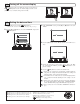
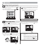
4 RECEIVING CALLS The unit used in the example pictures is a master monitor station. 4-1 1 2 Answering a call 3 When a call is received from an entrance station, security guard station, or door station, a call tone will sound and the STATUS LED blinks. If the station has a camera, a picture will be displayed on the monitor. If the station has a doorbell, a call tone sounds. (Communication is not possible.) When you are done talking, press the [ OFF] button. The STATUS LED will go off.
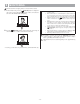
4-2 1 Door release Press the [ tion. ] button while in communication with the entrance sta- 2 Door release is activated at the entrance station. is displayed for approx. 5 sec. at the master monitor station. (This does not exactly correspond to the door release status of the entrance station.) • If the station has a camera, the door release will also activate during calling.
5 CALLING The unit used in the example pictures is a master monitor station. 5-1 Calling security guard stations 1 When calling all of the security guard stations, press the [ button while in the standby mode. 1 When calling one of the security guard stations, press the [ MENU] button, select "GUARD CALL", and press the [ MENU] button. 2 GUARD] Move the cursor to the security guard station to be called and press the [ MENU] button.
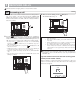
6 MONITORING The unit used in the example pictures is a master monitor station. 1 In the standby mode, press the [ MONITOR] button to display the video image from an individual door station. Audio can heard at the same time. The STATUS LED will light up. NOTES: 1. 2. 3. 4. 5. 2 Press the [ MONITOR] button again to display the video image in order from entrance 1. Audio can heard at the same time. 6. 7. If there is an operation such as a call, monitoring ends and the call operation begins.
7 OPERATION DURING COMMUNICATION AND MONITORING The unit used in the example pictures is a master monitor station. 7-1 1 ZOOM/WIDE switching Press the [ ZOOM/WIDE] button when a picture is displayed. • Switching between zoom ⇔ wide occurs each time the button is pressed. [Wide picture] NOTES: 1. 2. [Zoom picture] When the caller is not shown in the center of the picture, the zoom picture can be moved up, down, left, and right. (Refer to section 7-2.
7-4 Night illumination At night, the illuminator LED lights up during an entrance station or individual door station call. Also, the LED can be made to light up during monitoring of a individual door station. When a call is made from an entrance station or individual door station Lighting up the illuminator LED when monitoring an individual door station 1 1 If the call button of the entrance station or individual door station is pressed, the illuminator LED will light up.
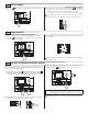
8 RECORDING AND PLAYING (MASTER MONITOR STATION) 8-1 Automatic recording If call is received from an entrance station or individual door station, resymbol blinks on cording starts automatically. During recording, the the screen. Zoom pictures (from 1st shot to 6th shot) 1st shot 2nd shot • Recording starts approximately 2 seconds after the CALL button of an entrance station or individual door station is pressed.
8-3 Playing recorded pictures If there are automatically recorded pictures, such as those taken while you were out, the STATUS LED blinks with a long interval during standby mode. 1 Press the [ REC/PLAY] button in the standby mode to display the picture with the most recent date and time. • displays on the screen when there are no recorded pictures. The status is displayed.
8-4 Saving recorded pictures 10 images can be saved from the recorded images (maximum of 40 images). Saved pictures are not overwritten. 1 2 Press the [ MONITOR] button. 07/16 JA N/01/2011 18:45 Display the picture that you want to save in the play-waiting screen. (Refer to section 8-3.) Press the [ MENU] button to display the save/erase selection screen. 07/16 JA N/01/2011 18:45 3 is displayed when saving is performed. If the picture has already been saved, the save is canceled.
9 ALARMS AND RELATED INFO. The unit used in the example pictures is a master monitor station. 9-1 OPTION button Pressing the [ OPTION] button allows for operation of connected units to be performed such as turning lights on and off. 9-2 Emergency alarm 1 Press and lock the emergency alarm switch (or when there is a line off trouble). 2 An alarm will sound from the residential station, and a warning signal will be sent to the security guard station. An emergency screen is displayed on the monitor.
9-3 1 External calls When a separately-installed sensor is activated or the CALL button is pressed, the alarm sounds, and the warning screen displays on the monitor and blinks. 2 Press the [ OFF] button or [ REC/PLAY] button ([ ton for GT-2H-L/GT-2H) to stop the alarm sound. OFF] but- • Only the alarm sounds at sub master monitor stations. 3UUUUUU 6(1625 $&7,9$7(' 5(6(7 NOTES: 1. 2. 3.
9-5 1 Canceling security setting after arrival (master monitor station) When the ABSENCE SECURITY setting in 9-4 is set, if an individual door is opened, a screen will display and the alarm will sound. 3 Restoration occurs when the security PIN is correct. • If the security PIN is not correct, "WRONG SECURITY PIN." will display.
10 CHANGING SETTINGS (MASTER MONITOR STATION) The screen may vary depending on the equipment being used. 10-1 Using the MENU 1 2 In the standby mode, press the [ 3 MENU] button. Press the [S] or [T] button to select "SETTINGS", and press the [ MENU] button. Press the [S], [T], [W], and [X] buttons in the "SETTINGS" screen to select the item to be confirmed, and press the [ MENU] button.
10-3 CALL TONE switching Separate sounds can be selected for entrance stations, individual door stations, and security guard stations from 5 sound types. 1 After performing steps 1 and 2 in section 10-1, select "CALL TONE" in the "SETTINGS" screen and press the [ MENU] button. 2 Select one from "ENTRANCE/DOOR/GUARD" in the "CALL TONE" screen, and press the [ MENU] button.
10-5 External call sound time duration setting Select the external call sound time duration. The initial setting is "10 MIN.". 1 2 3 After performing steps 1 and 2 in section 10-1, select "UTILITY" in the "SETTINGS" screen and press the [ MENU] button. Select the sound time in the "UTILITY-CALL TIMER" screen. Press the [ MENU] button to complete the settings. UTILITY-CALL TIMER Select "ALARM TIMER" in the "UTILITY" screen, and press the [ MENU] button. 10SEC. 1HOUR 1MIN. CONT. "CONT.
10-7 Individual door night illumination setting Select whether the door station illuminator LED is enabled or disabled. The initial setting is "ENABLE". 1 2 3 After performing steps 1 and 2 in section 10-1, select "DOOR" in the "SETTINGS" screen and press the [ MENU] button. Select "NIGHT ILLUMINATION" in the "DOOR" screen, and press the [ MENU] button. '225 &$// '85$7,21 > 6(& @ 1,*+7 ,//80,1$7,21 > (1$%/( @ - 22 - Select "ENABLE" or "DISABLE" in the "NIGHT ILLUMINATION" screen.
10-8 SECURITY PIN setting The security PIN to be used can be set when performing PRESENCE SECURITY and ABSENCE SECURITY setting. The initial setting is "DISABLE", when "ENABLE" is selected, the initial setting for the security PIN is [S], [X], [T], and [W]. 1 After performing steps 1 and 2 in section 10-1, select "SECURITY" in the "SETTINGS" screen and press the [ MENU] button. 2 Select "SECURITY PIN" in the "SECURITY" screen, and press the [ MENU] button.
10-9 DEPARTURE TIMER, ARRIVAL TIMER setting With ABSENCE SECURITY, the delay time from when an action causing a warning response is detected to when a warning is actually sent can be set. The initial setting is "60 SEC.". DEPARTURE TIMER = Time from when ABSENCE SECURITY is set to when user leaves ARRIVAL TIMER = Time from when user arrives to when ABSENCE SECURITY is canceled 1 After performing steps 1 and 2 in section 10-1, select "SECURITY" in the "SETTINGS" screen and press the [ MENU] button.
11 TECHNICAL PRECAUTIONS • Operating temperature: 0°C to +40°C (+32°F to +104°F) • The video image may distort when the door release is activated. But this is not a unit malfunction. • If a zoom/wide or pan/tilt operation is performed during communication with the entrance station, noise will be produced at the entrance station, but this is not a malfunction. • Cleaning: Clean the units with a soft cloth dampened with a neutral household cleanser. Do not use any abrasive cleaner or cloth.
Aiphone warrants that its products have no material or workmanship defects under normal use conditions for two years after delivery to the end user. Aiphone will perform repair or replacement free of charge if the product is defective and the warranty applies to the defect. Aiphone reserves unto itself the sole right to make the final decision whether there is a defect in materials and/or workmanship and whether or not the product is under warranty.