0505 A SECURITY WINDOW INTERCOM SYSTEM IMU-100, IAI-100, IAX-100, IME-100, ISE-100, IME-150 -1- INSTALLATION & OPERATION MANUAL
PRECAUTIONS General Prohibitions 1 1-1 English Prohibitions on Dismantling the Unit Prohibitions on Subjecting the Unit to Water General Precautions PACKAGE CONTENTS WARNING (Negligence could result in death or serious injury to people) MU-100 1. Do not dismantle or alter the unit as it could result in a fire or electric shock. 2. Do not connect the unit with any non-specified power source. Fire or electric shock could result. 3. Keep the unit away from water or any other liquid.
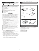
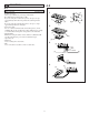
1-2 1-5 1 DR-100 2 1 3 Package contents (sensor ISE-100) Optional package 1. Sensor ISE-100 2. Screws AI-100 4 FF-100 6 Package contents (optional microphone IME-150) Optional package • Optional microphone IME-150 7 English 2 Package contents (acoustic tube IAX-100) 1. Acoustic tube IAX-100 2. Tube connector 3. Packing (semi-transparent) DESCRIPTION Features • A new acoustic tube system is used that combines an acoustic tube speaker with a noise canceling microphone.
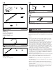
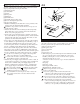
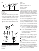
3 3-1 3-2 INSTALLATION 2 Cut [4] A [3] [5] [2] [2] [1] B [6] [7] C Cut 3 [1] [8] [4] [3] [5] [6] Operator units English [1] Main unit MU-100 Position under the desk. Can be installed with the mounting bracket provided. [2] Operation unit OU-100 Position on the left or right of the window desk, in a userfriendly location. [3] Power supply adapter PS-2420UL/2420S Position between the AC outlet and main unit in a location where it can be easily installed.
3-3 English Acoustic interface [1] Center of acoustic I/O tube [2] Customer [3] Barrier glass [4] Upper acoustic tube (2) [5] Upper acoustic tube (1) [6] Acoustic I/O tube [7] Lower acoustic tube [8] Driver unit [9] Tube fixer 1. Estimate the average height of customers, taking into account gender and age differences. Mark on the glass the height where the average customer's head would be during a conversation with the operator. Customers usually bend down a little when they talk.
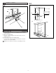
4 4-1 4-2 MOUNTING Main materials and tools English 1. Main materials •Double-sided tape Select a tape suitable for your usage environment. Recommendation: 4910 (made by 3M) If you are using the acoustic tube system, cut a piece of tape approximately 50cm (20") longer than the total length of the tubes. If you are using the optional microphone, cut a piece of tape approximately 10cm (4") in length. •Connection cable Use a 2-conductor shielded cable for the microphone, and an 18AWG cable for the speaker.
English Main unit Install the main unit under the counter or desk on the operator side. The cables from the other units will be connected at a later stage by temporarily removing the main unit. [1] Mounting bracket [2] Counter/desk [3] Switch [4] Front panel [5] Main unit [6] Terminal block [7] Transmit output speaker cable [8] Receive microphone input cable [9] Power supply adapter 1. Install the mounting bracket with the 4 screws provided, in the position where the main unit will be installed.
4-4 1. When the installation position is on the left as seen from the customer side, the acoustic I/O tube can be installed unchanged from its shipped configuration. When installing it on the right, while referring to the diagram, reverse the left/right direction of both slit plates of the acoustic I/O tube so that the direction of the sound I/O opening (slit) is reversed. 2. Open the driver unit cover, and remove from inside the driver main unit.
4-6 [4] Main unit [5] Base [6] Tube connector [7] Red label [8] Double-sided tape [9] Fixing base of the lower acoustic tube [10] Tube fixer [11] Counter sash,etc. [12] Acoustic tube main unit [13] Connection groove [14] Connection ridge • Temporarily insert the red label side of the acoustic tube into the connector on the bottom of the acoustic I/O tube, and align with the installation surface.
Guideline 4-8 Installation of the acoustic interface (upper acoustic tube) English [1] Used side (blue label side) [2] Discarded side (red label side) [3] Red label [4] Driver unit chassis [5] Fixing base 1. Measurements and cutting • Align the position of the top of the fixing base of the acoustic I/O tube that has already been installed with the position of the blue label side of the upper acoustic tube.
4-10 1 Acoustic interface wiring English [1] Speaker cable from main unit [2] Microphone cable from main unit [3] Temporary installation jig [4] Acoustic I/O tube main unit [5] Microphone cord [6] Chassis [7] Cord groove 1. Pull the transmit output speaker cable and receive microphone input cable that come from the main unit on the operator side through the chassis cable hole in the driver main unit that is fixed to the glass.
4-11 Not use connector [1] Red [2] [3] [4] Connection ridge [5] Upper acoustic tube (2) [6] Upper acoustic tube (1) [7] Acoustic I/O tube [8] Lower acoustic tube [9] Microphone cord [10] Chassis [11] Rubber seal [12] Acoustic tube [13] Set screw [14] Lead cable (driver unit) [15] Microphone cable [16] Speaker cable [17] Driver main unit 1.
4-12 4-13 1 2 1 [2] to Main unit [1] (-) White [1] (E) Shield (+) Red from External mic. [2] 2 [2] [3] 3 4 to Main unit Volume [3] (+) Black (-) White from External speaker Options English [1] Paging speaker [2] Terminal block [3] Sensor ISE-100 1. Use the instructions provided with the product when installing the paging speakers. There are many types of speakers available, such as wall speakers, ceiling speakers and horn speakers.
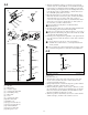
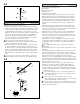
5 WIRING DIAGRAM 3 IME-100 [2] [3] 4 DR-100 E: Shield -: White +: Red H: Black C: White 2 OU-100 [1] 1 MU-100 5 AI-100 IAX-100 CON 1 [4] 12 [4] [4] [3] - + [5] 8 OP 7 ISE-100 +: Red SW: White -: Shield Page Speaker 6 PS-2420UL / 2420S - 14 -
5-1 5-3 Wiring English 1. Main unit MU-100 2. Operation unit OU-100 3. Gooseneck microphone IME-100 4. Driver unit DR-100 5. Acoustic I/O tube AI-100 and acoustic tube IAX-100 6. Power supply adapter PS-2420UL/2420S 7. Sensor ISE-100 8. Paging speaker (option) Suitable paging speakers have 4 to 6 Ω impedance and rated input of 3W or more, with a maximum input of 6W or more. [1] Special connection cord for operation unit and main unit (approximately 2m,6'6").
6 Names [1] POWER LED (green) [2] TALK switch (orange) [3] VOL switch (orange) [4] PAGE switch (orange) [5] Gooseneck microphone [6] Receive speaker [7] Headset connectors [8] POWER switch [9] VOX sensitivity knob [10] Transmit volume knob [11] Paging volume knob [12] Receive volume knob [13] Noise canceling control knob [14] Standby volume knob NAMES OU-100 [1] [5] [7] HEADSET SPEAKER MIC [3] [2] [4] [6] MU-100 [14] [12] [9] [10] [11] [13] [8] - 16 - English
7 [5] Adjust the sensitivity of the VOX circuit. • With the equipment arranged as it would be during use, have someone talk from the operator position. Adjust the VOX sensitivity knob by turning it clockwise so that it responds to the voice and the green LED illuminates. Adjust so that it illuminates when voice transmission starts and goes out when transmission ends. • When stable and the LED is flashing,the minimum knob position is the most suitable.
8 Operation English [1] Turn on the POWER switch of the main unit. The green lamp illuminates to show that electricity is being supplied and the system can be used. [2] Turn on the TALK switch of the operation unit. The orange lamp illuminates to show that communication is possible. •The voice from the customer side can be heard from the receive speaker built in to the operation unit. If a headset is connected, the receive sound is heard through the speaker(s) in the headset.
9 9-1 9-3 SPECIFICATIONS Specifications (acoustic interface kit IAI-100) English • Operating temperature: 0 °C to 40 °C • Acoustic output: Impedance: 4 Ω Rated input: 4.
WARRANTY Aiphone warrants its products to be free from defects of material and workmanship under normal use and service for a period of two years after delivery to the ultimate user and will repair free of charge or replace at no charge, should it become defective upon which examination shall disclose to be defective and under warranty.