
User guide
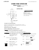


( ACTUAL TERMINAL LOCATION
C WALL MOUNTING INSTALLATION )
(T) Cable clamp
@ Wires for power supply
RED wire: Connect to Plus(+) wire of power
supply adaptor.
BLACK wire: Connect to Minus (—) wire of
power supply adaptor.
(3) Hole for mounting bracket
(4) Terminals [T] > 0 ■ Connect to door station
#1 (non-polarized)
(^Terminals QJ , : Connect to door station
#2 (non-polarized)
Terminals | Dj[ , [D2[ : For communication with
door
(7) Terminals [f] , , [j[] : Connect to room
station
(^Terminals [T^ , [U| : Connect to electric door
release
@ Cable clamp hole
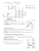
IBG-2AD, IBG-2CD
Attach the mounting bracket to wall or gang box. Insert the prongs of the
bracket into the holes of the body and pull the body downward. Be careful not to
attach the bracket upside down.
NOTE: Locate IBG-2AD master within convenient reach of AC receptacle —
IBG-2AD power supply wires length: About 18 cm (7-1/8")
IB-DA, IB-NA, IC-RA
* Remove screws and separate back
box from front cover.
* Mount the back box (or bracket)
to wall or gang box with supplied
screws.
* Wire two terminals and replace
front cover on the back box.
IBR-1
After wiring terminals, mount IBR-1
to wall or gang box with supplied
screws, as shown.
TERMINALS
CONNECTING WIRES
AC RECEPTACLE
POWER SUPPLY
ADAPTOR
IB-DA IB-NA
FRONT COVER SCREW (x2)
SCREW (x2) TERMINALS
CONNECTING
WIRES
IC-RA
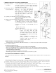
( WIRING )
Lay out your system in advance. Determine the exact location of each station. Make a sketch showing the number of
wires required from each station to other stations.
Refer to the chart below and select the proper wire gauge to meet your requirements.
Diameter of wire
0.5mm
0.65mm
0.8mm
24 AWG 22 AWG 20 AWG
Door station to IBG-2AD 90m
150m
230m 300' 450' 700'
IBG-2AD to IBG-2CD
45m 75m 115m
150' 230' 350'
-2-