83799600 A P1009YZ JK-DVF-AC Vandal-resistant Color Video Door Station with Access Control Keypad Platine vidéo couleur résistante au vandalisme avec clavier à codes rétro-éclairé Antivandalisme deurpost met kleurencamera en ingebouwd codeklavier JK-DVF-AC INSTALLATION & OPERATION MANUAL MANUEL D’INSTALLATION ET D’UTILISATION INSTALLATIE & GEBRUIKSHANDLEIDING JK-DVF-AC_ENG.
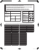
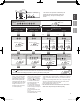
RECORD OF SETTINGS AND REGISTRATION DETAILS FOR ACCESS CONTROL (Please make sure to write down your settings below.) AIDE MEMOIRE DES PROGRAMMATIONS ENREGISTREES POUR LE CLAVIER (Faire en sorte de bien noter vos réglages ci-dessous.) LIJST MET GEPROGRAMMEERDE INSTELLINGEN EN CODES VOOR CODEKLAVIER (Zorg ervoor uw instellingen hieronder op te schrijven.
English English Thank you for selecting Aiphone for your communication and security needs. Please read this manual carefully before installation, and keep it in a safe place for future reference. * Refer to the “INSTALLATION & OPERATION MANUAL” for the JK-1MED or JK-1MD for complete information regarding this system. PRECAUTIONS Prohibition to Dismantle the Unit WARNING 1. The unit must be installed and wired by a qualified technician.
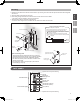
PACKAGE CONTENTS Transparent nameplate (x2) Special screwdriver Installation & Operation manual Français English Door station with Flush mount back box Nederlands MOUNTING Mounting locations "Do not install this unit in any of the following locations where lighting or the ambient environment could impact the display on the video monitor due to the characteristics of the door station's camera.
Mounting English 1. Detach the door station from the flush mount back box by removing the screws with the special screwdriver that is supplied with the unit. 2. Attach the flush mount back box to the wall. 3. Route wiring through the flush mount back box and connect wires to the door station. * See page 5 and 6 for details on wiring and connections. 4. Attach the door station to the flush mount back box. * Be sure to use the original screws to reattach the door station to the flush mount back box.
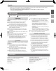
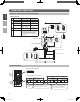
WIRING AND CONNECTIONS English Outline of connections and wiring distance Nederlands Français Wiring distance Power supply Diameter Distance A - 0.65 mm (22 AWG) 50m (165') - 1.0 mm (18 AWG) 100m (330') B 12 - 18V AC or DC or less 0.65 - 1.0 mm (22 - 18 AWG) 100m (330') 18 - 24V AC or DC 0.65 - 1.0 mm (22 - 18 AWG) 300m (980') C - 0.65 - 1.
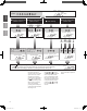
Connection examples English n Connection of Relay 1 only JK-1MED/1MD A1 A2 or L L NP Français JK-1MED 2 JK-1MD JK-DVF-AC 2 NP A2 Example of electric door strike connection (N/O) V V PB1 PB2 C T NO1 C1 NC1 NO2 C2 Example of automatic gate connection (N/O) NC2 NO1 C1 Example of electromagnetic door lock connection (N/C) NC1 N NO1 C1 NC1 NO2 C Electromagnetic door lock Electric door strike 2 NP 2 NP 2 NP Nederlands A1 2 NP or 2 NP or PS Automatic gate Request to exit/e
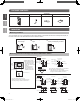
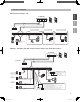
This section explains the settings of each function, including the master code for management, the user code for unlocking, the buzzer and the LEDs. About the setting mode: Enter master code twice to switch to the setting mode, and enter the following setting code to perform the settings for the desired function. After settings have been made, enter the following setting codes to continue the setting operation. Press to exit the setting mode.
Orange (L) Green (R) ) Input the setting code. Bleep, Bleep Setting the code Setting the master code (Default:1234) group 1 00 - 59 60 - 99 Input the setting code. Inputting of user number (ex.: 01) Inputting of user number (ex.
(orange) (green) Illumination Blinking Input the master code twice. English (Default : Français Setting the key illumination time (Default: 10 Sec.) Setting the relay output time (Default: 3 Sec.) When setting relay 1 Input the setting code. Nederlands Bleep, Bleep ) Illumination Blinking Reset Settings External output setting (Default: OFF) When setting relay 2 Input the setting code. Input the setting code. Illumination Blinking Bleep Input the setting code.
(orange) (green) Illumination Blinking Input the master code twice. (Default : Bleep, Bleep ) Illumination Blinking Bleep OFF ON Illumination Blinking Beep Bleep Input the setting code. Illumination Blinking Bleep OFF Illumination Blinking Input the setting code. ON Illumination Blinking Illumination Blinking Bleep Relays 1 and 2 are both linked Only relay 1 is linked Only relay 2 is linked Illumination Blinking Beep Nederlands Illumination Blinking Input the setting code.
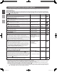
* Also refer to the “INSTALLATION & OPERATION MANUAL” for the master station (JK-1MED or JK1MD) connected to this unit regarding the operation of the video door station. A. Unlocking of user code When the registered user code has been input using the keypad (between 4 and 6 digits), the LED indicator (group 1: orange, group 2: green) lights up, the buzzer sounds, and the electric door strike is unlocked. Nederlands Français English OPERATION OF ACCESS CONTROL ex.
SPECIFICATIONS Français Nederlands Video door station • Power supply: Supplied from the master station • Camera unit: Complementary metal oxide semiconductor (CMOS) • Scanning lines: 525 lines • Minimum subject illumination: 5 Lux at 50 cm (1' 6") distance Access control keypad • Power supply: 12 - 24V AC 12 - 24V DC • Power consumption: DC: Max. 70mA AC: Max.