
Installation Manual

English Français Español Nederlands Italiano Deutsch
7
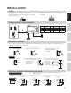
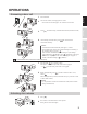
Place " UP" upwards
Mounting screw x 2
(Screw shaft: Ø4.1)
(Slotted Head: Ø8.2 or less
Height 3.0mm or less)
(not included)
Mounting screw x 2
(Screw shaft: Ø4.1)
(Slotted Head: Ø8.2 or less
Height 3.0mm or less)
(not included)
Main unit
1-gang box
Mounting frame
83.5 mm
(3-5/16")
83.5 mm
(3-5/16")
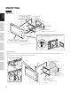
Mount the main unit on
the mounting frame,
and fit the front panel on.
Pry off the front panel with
a flathead screwdriver.
Removing the front panel
Flathead screwdriver
Front panel Main unit
Remove the main unit from
the mounting frame by
loosening the locking screws
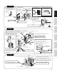
1
Fasten the mounting
frame to the wall.
2
Connect wires.
3
Tighten
Screwdriver
Loosen
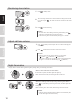
Drainage hole
Do not block the holes.
Insert a wire from the lower side.
<Back wiring>
<Bottom surface>
<Surface wiring>
Installation height
(center of the unit)
1,500 mm (5')
Wire slot
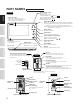
JO-DA
Loosen the special screw
with the special screwdriver,
and remove the front panel.
1
Fasten the unit to the mounting surface.
*Use board anchors or concrete plugs as needed.
4
Replace face plate and tighten
screw with included special
screwdriver.
5
75 mm
3''
Special
screwdriver
(included)
Loosen
Tighten
Vanda resistant
front panel
Anchor x 4
(Prepare anchors according to the size of the mounting screws.)
(not included)
The unit
Mounting screw × 4
(Screw shaft: Ø4.1)
(Slotted Head: Ø8.2 or less
Height 3.0mm or less)
(not included)
Special
screw
Insert the transparent name plate.
Peel off the protective seals on the plate (both sides).1.
Fill in the name on the transparent name plate.
Be sure to leave 25 mm (1") of white space on the right
end to account for insertion.
2.
Insert the filled-in transparent name plate as below
(indicated with in diagram).
3.
2
ABCDEFG
2 mm (1/8")
25 mm
(1")
Insert transparent
name plate here.
150 mm
5-15/16''
Drainage hole
Do not block the holes.
(The diameter and the depth of the holes on the wall depend on
the anchors suitable for the mounting screws used.)
50 mm
1-31/32''
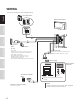
Connect wires to the unit.
3
70 mm
2-3/4''
JO-DV
110 mm
4-3/8''
180mm
7-3/32''
45 mm
1-25/32''
Vandal resistant front panel with the unit attached
Flush mount back box
(included)
Transparent name plate
Special
screw x 4
(included)
Hexagonal wrench (included)
Tighten
Loosen
Install the flush mount back box in
the wall, and then connect the wires to
the unit with the terminal cover open.
1
Insert the transparent name plate.
*See above JO-DV for details.
2
Fasten the front panel to the back
box with the special screws.
3
JO-DVF