JP-DA, JP-DV, JP-DVF VIDEO DOOR STATION POSTE DE PORTE VIDÉO VIDEO PORTERO VIDEODEURPOST POSTAZIONE VIDEOCITOFONICA ESTERNA INSTALLATION MANUAL MANUEL D’INSTALLATION MANUAL DE INSTALACIÓN INSTALLATIEHANDLEIDING MANUALE D’INSTALLAZIONE JP-DA JP-DVF Video door station Poste de porte vidéo Video portero Videodeurpost met kunststof opbouwbehuizing Postazione videocitofonica esterna Vandal-resistant video door station Portier vidéo résistant au vandalisme Video portero antivandálico Videodeurpost met inox a
English PRECAUTIONS General Prohibitions Prohibition to Dismantle the Unit Prohibition on Subjecting the Unit to Water WARNING CAUTION Français Negligence could result in death or serious injury. Español General Precautions Negligence could result in injury to people or damage to property. 1. Do not dismantle or alter the unit. Fire or electric shock could result. 1. Before turning on power, make sure wires are not crossed or shorted. If not, fire or electric shock could result. 2.
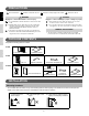
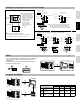
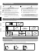
Mounting positions and image view area ◇ Wide picture ◇ Wide picture Approx. 1,300 mm (4' 3") Up/Down Mounting position 1,500 mm (5') Approx. 2,200 mm (7' 2") Unit center Approx. 1,300 mm (4' 3") Approx. 900 mm (2' 12") Mounting position 1,300 mm (4' 3") Approx. 2,000 mm (6' 7") Approx. 1,300 mm (4' 3") 1,500 mm (5') Unit center Approx. 700 mm (2' 4") 1,300 mm (4' 3") 500 mm (20") 500 mm (20") Approx. 170° 500 mm (20") Approx. 600 mm (2') Français Left/Right ◇ Zoom picture Approx.
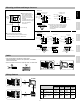
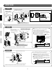
English MOUNTING JP-DA Mounting screw × 2 (not included) Screw shaft: Ø4.1 or less Slotted head: Ø8.2 or less, 3.0mm or less in height ① Removing the main unit from the mounting frame ② Place " Main unit UP" upwards Français Remove the main unit. (Loosen the locking screws.) ③ Mount the main unit on the mounting frame, and fit the front panel on. Removing the front panel 83.
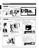
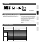
WIRING A2 JP-DA JP-DV 2 English A1 1A1 NP 1A2 JP-DVF JP-4MED NP: Non-polarized Français TECHNICAL PRECAUTIONS • Door station is weather resistant. However, do not spray high pressure • Cleaning: water on door station directly. Unit trouble could result.
English PRECAUTIONS Mesures générales dʼinterdiction Interdiction de démonter lʼappareil Interdiction dʼexposer lʼappareil à lʼeau AVERTISSEMENT ATTENTION Le non-respect de cet avertissement risque dʼentraîner des blessures graves, voire mortelles. Le non-respect de cet avertissement risque dʼentraîner des blessures ou des dégâts matériels. 1. Avant de brancher le bloc dʼalimentation, vérifiez que les fils ne sont pas croisés ou en court-circuit.
Positions de montage et zone de vision de l’image ◇ Image plein écran ◇ Image plein écran Environ 1 300 mm Environ 2 000 mm Centre de lʼunité Environ 1 300 mm Environ 1 300 mm Environ 900 mm 1 500 mm Centre de lʼunité Environ 700 mm 1 300 mm 500 mm 500 mm Gauche/droite ◆ Une zone de couverture s’affiche, d’environ 170° avec un rayon de 500 mm à partir de la caméra. (La plage d’affichage est une estimation brute et peut varier suite à l’environnement de l’installation.
English MONTAGE JP-DA Vis de montage × 2 (non inclus) Diamètre de vis: Ø4,1 maximum Tête fendue: Ø 8,2 maximum, 3,0 mm de hauteur maximum ① Retirer l’unité principale de son étrier ② Placez le “ Unité principale HAUT”vers le haut Retrait de la face avant Retirez l’unité principale. (Dévissez les vis de montage). Français ③ Montez l’unité principale sur l’étrier et fixez la face avant.
CABLAGE 2 A2 JP-DA JP-DV English A1 1A1 NP 1A2 JP-DVF JP-4MED NP: non polarisé Français PRECAUTIONS TECHNIQUES • Le poste de porte résiste aux intempéries.
English PRECAUCIONES Prohibiciones generales Prohibición de desmantelar la unidad Prohibición de exponer la unidad al agua ADVERTENCIA PRECAUCIÓN No seguir estas instrucciones podría provocar lesiones graves o incluso la muerte. No seguir estas instrucciones podría causar daños físicos o materiales. 1. Antes de encender la unidad, asegúrese de que no haya ningún cable cruzado o en cortocircuito. De lo contrario, podrían producirse incendios o descargas eléctricas. Français 1.
Posiciones de montaje y área de visión ◇ Imagen wide ◇ Imagen wide Aprox. 1.300 mm Arriba/Abajo Aprox. 2.200 mm Posición de montaje 1.500 mm Centro de la unidad Aprox. 1.300 mm Aprox. 900 mm Aprox. 1.300 mm 1.500 mm Centro de la unidad Aprox. 700 mm 1.300 mm 500 mm 500 mm Izquierda/Derecha ◆ Se visualiza un área sobre un alcance de aprox. 170° en un radio de 500 mm desde la cámara. (El alcance de la visualización es un cálculo aproximado y puede cambiar debido al ambiente de la instalación.
English MONTAJE JP-DA Tornillo de montaje × 2 (no incluido) Eje del tornillo: Ø4,1 o menos Cabezal con ranuras: Ø8,2 o menos, 3,0 mm o menos de altura ① Retirando la unidad principal del cuadro de montaje ② Coloque " Unidad principal ARRIBA" hacia arriba Para retirar el panel frontal Retire la unidad principal. (Afloje los tornillos de bloqueo.) Français ③ Monte la unidad principal en el cuadro de montaje y coloque el panel frontal.
CABLEADO 2 A2 JP-DA JP-DV English A1 1A1 NP 1A2 JP-DVF JP-4MED NP: No polarizado • El portero es resistente al ambiente.
English VOORZORGSMAATREGELEN Algemeen verbod Verbod om het toestel te demonteren Verbod om het toestel met water in contact te brengen WAARSCHUWING OPGELET Niet-naleving kan de dood of ernstig lichamelijk letsel veroorzaken. Niet-naleving kan lichamelijk letsel of materiële schade veroorzaken. 1. Controleer of de draden niet gekruist of kortgesloten zijn alvorens de stroom in te schakelen. Zo niet kan brand of een elektrische schok ontstaan. Français 1. Demonteer of verander het toestel niet.
Montagestanden en gezichtsveld ◇ Breedbeeld ◇ Breedbeeld Ong. 1.300 mm English ◆ Voorwerpen aan de rand van het beeld zien er kleiner uit door de grotere vervorming t.o.v. het centrale gedeelte De weergegeven maten zijn indicatief Omhoog/Omlaag Montageschroeven 1.500 mm Ong. 2.200 mm Montageschroeven 1.300 mm Ong. 2.000 mm Midden van het toestel Ong. 1.300 mm Ong. 1.300 mm Ong. 900 mm 1.500 mm Midden van het toestel Ong. 700 mm 500 mm 1.
English MONTAGE JP-DA Montageschroeven × 2 (niet meegeleverd) Schroefas: Ø 4,1 of minder Kop: Ø 8,2 of minder, 3,0 mm of minder hoog ② ① De deurpost van het montagekader verwijderen. Plaats " Deurpost UP" omhoog Afwerkkader verwijderen Draai de schroeven los om het kader te demonteren Français ③ Monteer de deurpost terug op het montagekader, en plaats er het afwerkkader op.
BEDRADING 2 A2 JP-DA JP-DV English A1 1A1 NP 1A2 JP-DVF JP-4MED NP: Niet-gepolariseerd • De buitenpost is weerbestendig, maar spuit geen water onder hoge Français TECHNISCHE VOORZORGSMAATREGELEN • Reiniging: druk rechtstreeks op de buitenpost. Dit kan het toestel beschadigen. ◆ Español ◆ Nederlands Maak de toestellen met een zachte doek en een neutraal reinigingsmiddel schoon. Gebruik geen schoonmaakspray rechtstreeks op het toestel. Gebruik geen schurend reinigingsmiddel of doek.
English PRECAUZIONI Divieti generici Divieto di smontare lʼunità Divieto di esporre lʼunità allʼacqua AVVERTENZA ATTENZIONE Il mancato rispetto di quanto indicato potrebbe causare lesioni gravi o incidenti anche mortali. Il mancato rispetto di quanto indicato potrebbe causare lesioni alle persone o danni alle cose. 1. Prima di accendere lʼunità, assicurarsi che i cavi non siano incrociati né in cortocircuito. In caso contrario, si correrebbe il rischio di un incendio o di scarica elettrica.
Posizioni di montaggio ed area di visualizzazione dell’immagine ◇ Immagine ripresa nella modalità grandangolo Circa 1.300 mm ◇ Immagine ripresa nella modalità ingrandimento Su/Giù Circa 2.200 mm Circa 2.000 mm Centro dell'unità Circa 1.300 mm Circa 900 mm Circa 1.300 mm 1.500 mm Centro dell'unità Circa 700 mm 1.300 mm 500 mm 500 mm Sinistra/Destra ◆ Viene visualizzata un'area di circa 170° in un raggio di 500 mm ripresa dall'occhio della telecamera.
English MONTAGGIO JP-DA Vite di montaggio × 2 (non incluse) Albero vite: Ø 4,1 o meno Testa scanalata: Ø 8,2 o meno, 3,0 mm o meno di altezza ① Rimozione dell'unità principale dal telaio di montaggio ② Posizionare la parte con il simbolo " UP" verso l'alto Rimozione del pannello anteriore Unità principale Rimuovere l'unità principale. (Allentare le viti di bloccaggio).
CABLAGGIO 2 A2 JP-DA JP-DV English A1 1A1 NP 1A2 JP-DVF JP-4MED NP: Non polarizzato Français PRECAUZIONI TECNICHE • La postazione videocitofonica esterna è resistente alle intemperie.
WARRANTY English Aiphone warrants its products to be free from defects of material and workmanship under normal use and service for a period of two years after delivery to the ultimate user and will repair free of charge or replace at no charge, should it become defective upon which examination shall disclose to be defective and under warranty.
GARANTIE Nederlands Aiphone waarborgt zijn producten tegen materiaal- en fabricagefouten bij normaal gebruik en onderhoud gedurende een periode van twee jaar na levering aan de eindgebruiker, en zal het product kosteloos herstellen of vervangen indien na onderzoek blijkt dat het toestel een defect heeft dat onder de waarborg valt. Aiphone behoudt zich het recht voor als enige definitief te bepalen of er al dan niet sprake is van een materiaal- en/of fabricagefout en of het product nog onder waarborg is.
http://www.aiphone.net/ Issue Date: Oct. 2014 FK2096 A P1014 AZ 56125 AIPHONE CO., LTD.