
User Manual
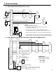
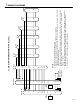

3a. SINGLE MASTER SYSTEM, NO ALL CALL
1
2
3
4
5
~
20
E
E
E
E
-
C
R
Y
P1
P2
P3
+
-
LAF-20C
+
-
PS-1225UL
LE-A
1
E
-
LE-A
LE-D
Pg. 3
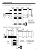
3b. DUAL MASTER SYSTEM WITH MASTER-TO-MASTER COMMUNICATION
1
E
-
1
E
-
LE-D
1
E
-
NOTES:
Two wiring method can be used:
1. 2 conductor homerun to each sub station from the master.
(Single master system only.)
2. Run multi-conductor wire in a daisy-chained fashion with 2
common wires (E & -) plus one individual wire per station on the run.
Remove jumpers between E & - when daisy-chained method is used.
3. To protect system from power surge, install SA-1 arrestors at master
station. One SA-1 is required for every two wires connected to master.
1
2
3
~
19
E
-
C
20
R
Y
P1
P2
P3
+
-
LAF-20CA
+
-
PS-1225UL
LE-DA
1
E
-
LE-DA
LE-DA
1
E
-
1
E
-
LE-DA
1
E
-
LAF-20CA
1
2
3
~
19
E
-
20
C
R
Y
P1
P2
P3
+
-
Master-to-master
communication is shown
on channel 20 of each
master.
Y, P1, P2, P3
terminals used only if
All Call Adaptors are
included.
WIRING DIAGRAMS
WIRING NOTE:
The following sub stations
are wired as shown above:
· LE-A, LE-AN
· LE-B, LE-BN
· LE-D, LE-DA
Remove
E/- jumpers
SA-
1
SA-
1
SA-1 for optional
surge protection
(See note #3.)
SA-
1
All "E" terminals are
common internally.
RY-AC
Red
Blk
Wht
Yellow
To external signalling device and power
(E.g. Station #19 will actvate ext. device
when it calls in to master.)
RY-AC for external signalling
when sub calls