FK1721 A P0311 OQ GT-AC Access Control keypad Module Module clavier à codes rétro-éclairé GH / GT-Codeschlossmodul Módulo de teclado de control de acceso Codeklavier-module GT-AC INSTALLATION & OPERATION MANUAL NOTICE D'INSTALLATION ET D'UTILISATION INSTALLATIONS- UND BEDIENUNGSANLEITUNG MANUAL DE INSTALACIÓN Y USO INSTALLATIE & GEBRUIKSHANDLEIDING
RECORD OF SETTINGS AND REGISTRATION DETAILS (Please make sure to write down your settings below.) AIDE MEMOIRE DES PROGRAMMATIONS ENREGISTREES (Faire en sorte de bien noter vos réglages ci-dessous.) VERZEICHNIS DER EINSTELLUNGEN UND REGISTRIERUNGSDETAILS (Bitte notieren Sie unten Ihre Einstellungen.) DATOS DE CONFIGURACIÓN Y DETALLES DE LOS REGISTROS (Asegúrese de apuntar los valores de ajuste abajo.) LIJST MET GEPROGRAMMEERDE INSTELLINGEN EN CODES (Zorg ervoor uw instellingen hieronder op te schrijven.
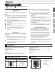
English PRECAUTIONS Prohibition to Dismantle the Unit WARNING 2. Do not install or make any wire terminations while power supply is plugged in. It can cause electrical 1. This product, being a control unit of door release, should not be used as a crime-prevention device. 2. This product is weather-resistant, but do not spray high-pressure water on it. Unit trouble could result. 3. The product becomes inoperative during power failure. 4.
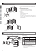
MOUNTING English The illustrations below use the GH system. 1. Fix the mounting bracket to the back (or surface-mount) 1 box. 2. Connect the wires to the unit. Français 3. Mount GT-AC to the front frame. • Mount GT-AC from behind the front frame. • Insert the notch into the slots on both sides. 4. Options Deutsch 2 a.Rain hood b.Hooded surface-mount box 3 c.
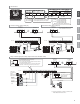
Terminal names Back view of GT-AC User group1 relay 1 V V PB1 PB2 User group2 relay 2 N/C contact N/C contact Timer C T NO1 C1 NC1 NO2 N/O contact Request to exit/entry button・ Timer Between 12 and 24V AC Between 12 and 24V DC ・ Minimum overload :100mV DC, 0.1mA or below ・ Contact capacity: 30V DC, 0.
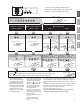
Deutsch Français English FUNCTIONS SETTING UP This section explains the settings of each function, including the master code for management, the user code for unlocking, the buzzer and the LEDs. About the setting mode: Enter master code twice to switch to the setting mode, and enter the following setting code to perform the settings for the desired function. After settings have been made, enter the following setting codes to continue the setting to exit the setting mode. operation.
Orange (L) The result of each operation is indicated by the Green (R) lighting up of the LED indicators on the upper section (orange) (green) Illumination Blinking Input the master code twice. ) Setting the master code (Default㧦1234) group 1 Setting the code 00 - 59 60 - 99 Input the setting code. Inputting of user number (ex.: 01) Inputting of user number (ex.
(orange) (green) Illumination Blinking Input the master code twice. English (Default : Français Setting the key illumination time (Default: 10 Sec.) Setting the relay output time (Default: 3 Sec.) When setting relay 1 Input the setting code. Deutsch Bleep, Bleep ) Illumination Blinking Reset Settings When setting relay 2 Input the setting code. Input the setting code. Illumination Blinking Illumination Blinking Bleep Input the setting code. Bleep Input the setting code.
(orange) (green) Illumination Blinking Input the master code twice. (Default : Bleep, Bleep ) Illumination Blinking Bleep OFF ON Input the setting code. Input the setting code. Illumination Blinking Bleep OFF ON Illumination Blinking Bleep Relays 1 and 2 are both linked Only relay 1 is linked Only relay 2 is linked Deutsch Illumination Blinking Input the setting code. Operation sound settings (Default: ON) Français Input the setting code.
Français English OPERATIONS A. Unlocking of user code When the registered user code has been input using the keypad (between 4 and 6 digits), the LED indicator (group 1: orange, group 2: green) lights up, the buzzer sounds, and the electric door strike is unlocked. ex.