
Installation Instructions


NOTE:
Release contacts on the JF-2MED are from
the 4-pin connector included with the unit.
Connect Red & Brown wires as shown.
Orange & Yellow wires are not used.
Release contacts on the JO-1MD/1FD
are L/L terminals.
A1
A2
B1
B2
S
S
DC 18V
+
-
RELEASE
(L)Brn
(L)Red
JF-2MED
JO-1MD/1FD
Door Station
A1
A2
PS-1820UL
+
-
.
Red
Blk
Brn
Org
Yel
COM
N/O
N/C
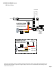
Use Normally Open
contact for electric strike
ELECTRIC STRIKE
WIRING METHOD:
JF/JO SERIES:
PS-1820UL
+
-
.
Red
Blk
Brn
Org
Yel
COM
N/O
N/C
Use Normally Closed
contact for magnetic lock
MAGNETIC LOCK
WIRING METHOD:
A1
A2
B1
B2
S
S
DC 18V
+
-
RELEASE
(L)Brn
(L)Red
Add jumper
wire from
L/Brn to +
Add
jumper
wire from
L/Brn to +
NOTE:
Only wiring pertaining to connection of door
release relay is shown here. For complete system
information, please consult the installation manual
for the system you are installing.
+ -
LOCK
POWER
+ -
LOCK
POWER
JF-2MED
JO-1MD/1FD
WIRING DIAGRAMS (cont):
Page 3
NOTE: The door release contacts on the station are rated at 24V AC/DC, 500mA. The RY-1824L should be used in any
application where the strike or maglock has a higher voltage or draws more current. Otherwise, internal damage to the
master station could occur.
RY-1824L
RY-1824L