Air Comm Systems, Inc. Single Audio Mixer Panel Operations and Installation Manual ACS 2010 AirComm Revision 1.3 Air Comm Systems Inc. 1640 W. Acoma Blvd., Suite A-118 Lake Havasu City, AZ 86403 Phone (928) 854-5402 Airborne Audio Products FAX (928) 854-8919 E-Mail aircomminc@aol.
ACS 2010 Operations and Installation Manual Table of Contents n Installation Physical and Operating Specifications Physical Dimensions Interface Schematic n Operation Front Panel Controls Front Panel Controls Pictorial n Page 9 Warranty Information Warranty Information n Page 6-7 Page 8 Addendum Instruction for Continued Airworthiness n Page 3 Page 4 Page 5 Page 10 Supplemental Information Product Schematics Air Comm Systems, Inc.
ACS 2010 Operations and Installation Manual Physical and Operating Specifications n Physical Specifications 5.75 in. (14.61cm) W 1.25 lb. (.56kg) 1.50 in.( 3.81 cm) H 5.03 in.(12.77cm) D Dzus rail mount Panel mounted - transmit = rotary switch, audio inputs = potentiometer, volume control = dual potentiometer Edge lit front panel per MIL-P-7738E, type 3. Capable of connection to dimmer bus for adjustment. Amber transmit light indicates when unit is in transmit mode.
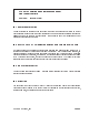
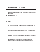
ACS 2010 Operations and Installation Manual Physical Dimensions n Physical Dimension Outline for mounting Physical Installation The ACS 2010 is designed to be Dzus mounted and should be installed in the aircraft using the DC37SL-F Installation kit that is included. The above outline drawing of the unit with dimensions will facilitate the installation.
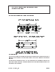
ACS 2010 Operations and Installation Manual Interface Schematic n Connector Pin-out ACS 2010 AUDIO PANEL A B C D E F G H J K L M N P R S T U V W X Y Z a b c 14 OR 28VDC POWER IN MICROPHONE HI TRANSMIT KEY ICS KEY HEADPHONE AUDIO SHIELD GROUND INPUT 1 MIC HI INPUT 1 KEY INPUT 1 AUDIO INPUT 2 MIC HI INPUT 2 KEY INPUT 2 AUDIO INPUT 3 MIC HI INPUT 3 KEY INPUT 3 AUDIO INPUT 4 MIC HI INPUT 4 KEY INPUT 4 AUDIO INPUT 5 MIC HI INPUT 5 KEY INPUT 5 AUDIO PA MIC HI PA KEY/MXD AUDIO ICS BUSS LIGHT DIM POWER GROUND
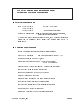
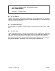
ACS 2010 Operations and Installation Manual Front Panel Controls ( See Figure 1 Page 8 for pictorial ) n 1 - Norm - Emer Switch This switch controls the operations of the audio panel in the event of an audio amplifier failure. In the up position (NORM) the audio panel is in normal operating mode. In the down position (EMER) all audios are summed and then fed directly to the headphones. This enables the use of the transmitters and other equipment during audio amplifier failure.
ACS 2010 Operations and Installation Manual Front Panel Controls ( See Figure 1 Page 8 for pictorial ) n 5 - Mic Selector This rotary switch performs three functions simultaneously. It (a) connects the mic to the selected transmitter (b) selects the associated keyline, and (c) selects the associated audio (if not already selected using the audio select-mute volume pot).
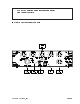
ACS 2010 Operations and Installation Manual Front Panel Controls n Figure 1 - Front Panel Controls Air Comm Systems, Inc.
ACS 2010 Operations and Installation Manual Addendum Instruction for Continued Airworthiness Instruction for continued airworthiness for Audio Mixer Panel Model ACS-2010 Series, Part Number 1004-000. GENERAL DESCRIPTION: The Audio Mixer Panel consists of a Dzus mounting located in the cockpit or cabin area which provides access to multiple radios for transmitting and receiving. It also provides intercom, both keyed and VOX between other audio mixer panels or slave units located elsewhere in the aircraft.
ACS 2010 Operations and Installation Manual Warranty Information n Warranty Information Air Comm Systems, Inc.