0000 / 12000 BTU Room Air Conditioner with Heat Pump OPERATING AND INSTALLATION MANUAL Models: KC-30H / KC-35H Thank you for selecting Soleus Air. To ensure proper operation, please read this manual and keep it for future reference.
TABLE OF CONTENTS INTRODUCTION……………………………..…………………………………….…................................1 SAFETY INFORMATION………………………………………………....…………........…..……......….1 NORMAL CARE AND MAINTENANCE……………………………………………….…..………….…3 INSTALLATION REQUIREMENTS………………………………………………..……….……….....…5 ELECTRICAL REQUIREMENTS…………………………………...………..………..…..................……6 INSTALLATION INSTRUCTIONS………………………………………………..……….……….…..…8 THROUGH-THE-WALL CABINET INSTRUCTIONS..……………………………………….……......10 COMPLETE INSTALLATION INSTRUCTIONS..
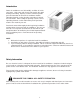
Introduction Room air conditioners cool, dehumidify, and filter air inside your home. Heat pump and electric heat models offer both heating and cooling. Opening sections of manual provide general information for all room air conditioner models. Operating Controls section describes operation of controls for each model. After reading the opening sections, turn to Operating Controls section and find the panel layout that matches the model of your unit.
OWNER'S PRODUCT IDENTIFICATION WARNING MODEL NUMBER To prevent heat related illness or death, do not use this device for unattended cooling of persons or animals unable to react to product failure. Failure of unattended air conditioner may result in extreme heat in area intended for cooling, causing heatrelated illness or death of persons or animals.
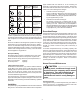
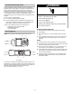
Unit Plug Type Receptacle Required page included with this manual or in the mounting kit assembly. Follow these instructions carefully. Keep these instructions with this manual for future reference. Your unit will be one of the following three designs: Circuit Rating, Voltage Breaker, Time Rating On Delay Fuse Nameplate NEMA No. 5-15P NEMA No. 5-15R 125V-15AMP 115V • NEMA No. 6-15P NEMA No. 6-15R 250V-15AMP 230/208V rated at 12 amperes or less NEMA No. 6-20P NEMA No.
Note: The life of your unit may be greatly reduced if you live in a salt air or other corrosive type environment. Under these conditions, the unit should be removed from its case and completely cleaned at least once a year. At that time any scratches or blisters on the painted surfaces should be sanded and repainted. Placing an algaecide tablet in the outdoor side of the unit’s basepan is suggested in humid areas where algae formation is common.
IMPORTANT SAFETY INSTRUCTIONS WARNING: To reduce the risk of fire, electrical shock or injury when using your air conditioner, follow these basic precautions: Plug into a grounded 3 prong outlet. Do not use an extension cord. Do not remove ground prong. Unplug air conditioner before servicing. Do not use an adapter. Use two or more people to move and install air conditioner.
Window installation Electrical Requirements Window opening measurements: ■ 27" min. to 39" max. (68.6 cm to 99 cm) opening width. ■ WARNING 16¹⁄₄" min. (41.3 cm) opening height. Electrical Shock Hazard Plug into a grounded 3 prong outlet. Do not remove ground prong. A Do not use an adapter. B Do not use an extension cord. Failure to follow these instructions can result in death, fire, or electrical shock. A. 27" min. (68.6 cm) B. 16¹⁄₄" min. (41.
WARNING Recommended grounding method This air conditioner must be grounded. This air conditioner is equipped with a power supply cord having a grounded 3 prong plug. To minimize possible shock hazard, the cord must be plugged into a mating, grounded 3 prong outlet, grounded in accordance with all local codes and ordinances. If a mating outlet is not available, it is the customer's responsibility to have a properly grounded 3 prong outlet installed by a qualified electrical installer.
INSTALLATION INSTRUCTIONS Unpacking 3. Remove front panel by removed 2 phillips screws on both bottom left right sides of front. 3A: Remove both knobs from control panel. 4. Remove ground screw and ground wire from front of air conditioner base. Save ground screw. WARNING Excessive Weight Hazard Use two or more people to move and install air conditioner. Failure to do so can result in back or other injury. A Remove packaging materials ■ Remove and dispose of/recycle all packaging materials.
Attach Side Curtains Attach foam adhesive seal 1. Locate provided bag of screws. 2. Insert top and then bottom of right-hand curtain housing in top and bottom curtain guides on air conditioner cabinet. Attach foam adhesive seal along the bottom of the curtain bottom channel. Back View A B A B A. Curtain housing B. Foam adhesive seal Install Cabinet into Window A. Curtain housing B. Curtain guides Bottom View A ■ Handle air conditioner gently.
4. Use a ³⁄₁₆" drill bit to drill 3 starter holes 1/2" deep through the 3 holes in the cabinet and into the windowsill. 5. Attach cabinet to windowsill with 3 - #10 x 1/2" pan-head Phillips screws. 2. Insert one of the #10 x ³⁄₄" round-head screws through hole and into lower window sash. Insert one of the #10 x ³⁄₄" round-head screws through threaded hole in top of curtain and one in bottom of curtain. A B B A A A. #10 x ³⁄₄" round-head screw B. Hole for #10 x ³⁄₄" round-head screw A.
Option 1—Wood, metal or plastic molding ■ Use 1" (2.5 cm) or thicker lumber for wood frame. When you are using wood, metal or plastic molding, the wood frame should line up with inside wall as shown. A A B C B D C A. Outside width B. Outside height C. Depth A. Molding B. Inside wall 4. Apply wood preservative to the outside exposed surface. 5. Insert the frame in the wall opening. Square and level frame. 6. Attach frame securely to the wall. C. Wood frame D.
Complete Installation NOTE: Handle air conditioner gently. 1. Make sure the free end of the ground wire is outside of the cabinet. Position ground wire pointing straight up. Put excess ground wire between coil and air conditioner cabinet. WARNING A Excessive Weight Hazard + Use two or more people to move and install air conditioner. Failure to do so can result in back or other injury. + B A. Green ground wire B. Ground screw 2. Insert air conditioner into cabinet.
General Operating Instructions While operation of all units is similar, controls vary slightly from model to model. Operating Controls section shows control panel of unit purchased and gives detailed information about operation of controls. To install, remove the unit chassis from the outer case. Insert the condensate drain cup through the recessed ½” hole on the back center of the outer case. Once inserted, place a ½” diameter hose or tube on the drain cup bottom spout.
Operating Controls COMFORT ZONETM AND HEAT PUMP MODELS Fan Control OFF – Completely shuts off the unit. To prevent blowing fuses, wait two minutes after turning the unit off before turning it on again. LOW COOL – Filters and circulates room air with the fan running continuously on low speed. Also cools and dehumidifies while the compressor is running. Select this setting for quiet cooling operation. HIGH COOL – Filters and circulates room air with the fan running continuously on high speed.
Before Calling Service To reduce the risk of electric shock, personal injury, or death, turn the fan control to the off position and remove the unit plug from the wall outlet before doing any inspection or maintenance work. The following is a list of problems that are sometimes encountered when using a room air conditioner. Possible cause and suggested remedies are given for each problem. If the problem cannot be fixed using the suggested remedies, see WHEN SERVICE IS REQUIRED section.
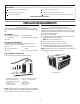
Thru-wall Installation Instructions for GREE® brand Room Air Conditioner Introduction This instruction sheet provides guidelines for installing a compact air conditioner through an outside wall. 22 3/5'' CAUTION Installing an air conditioner through a wall requires extensive carpentry and/or masonry experience. Thru-wall installations performed by inexperienced or unqualified individuals can result in costly damage to home.
Placement of Outer Case in Opening Place outer case in opening, flush against one side of opening. Use carpenter’s level and ensure case is level from side to side and has a 3/8-inch slope from front to back (back of case must be 3/8-inch lower than front to ensure proper condensate drainage). If needed, use shims to level case (from side to side) and to obtain proper back slope. 15 9/16" Front of case must project ¾-inch (minimum) beyond inside wall in order to attach air conditioner front frame.
Installation in Wall Thicker Than 5 ½inches The side louvers in outer case provide ventilation to air conditioner compressor and fan motor and must not be blocked. When installing unit in a wall over 5 1/2-inches thick, provisions must be made in wall opening to ensure free air flow to the side louvers. This can be accomplished by chamfering the vertical portions of the outside opening as shown. Ventilation louvers on top of case must not be obstructed.
Specifications Model KC-30H KC-35H Cooling Capacity (BTU/HR) 9500/9700 11400/11600 Heating Capacity (BTU/HR) 8300/8500 10100/10500 Electric Heat (BTU/HR) 8500/10700 8500/10700 Rated Voltage 208/230V~ 208/230V~ 60Hz 60Hz Design Pressure Lowside 150 P.S.I. 150 P.S.I. Design Pressure Highside 330 P.S.I. 380 P.S.I. Cooling AMPS 4.8/4.6 5.9/5.5 Cooling Watts 970/990 1210/1235 Cooling EER 9.8 9.4 Heating AMPS 4.5/4.2 5.8/5.1 Heating Watts 850/870 1100/1140 Heating EER 9.
Warranty Soleus International Inc. warrants the accompanying Soleus Air 10000 / 12000BTU Heat Pump Room Air Conditioner (KC-30H / KC-35H) to be free of defects in material and workmanship for the applications specified in its operation instruction for the period of parts specified below. 5 YEARS FOR COMPRESSOR 1 YEAR FOR OTHER COMPONENTS This warranty shall not apply to broken or marred cabinets, accessories, knobs, filters or routine maintenance.