User Instruction Manual ZT-1017-VS ZT-6000-VS FOR SALES, SERVICE OR TECH SUPPORT CALL: 1800-BUY-RIVET or 1-800-289-7483
CONTENTS Safety Page 3 Specifications Page 3 Preparing the tool for service Page 4 Jaw Cleaning Procedure / Jam Remedy Page 5 Proper Jaw Pusher Selection Page 5 Air supply Page 6 Preventive Maintenance / Service Daily Weekly Head Assembly Pneumatic Piston Assembly Oil Change/Replacement Procedure Valve Spool Assembly Trigger Page Page Page Page Page Page Page 6 6 7 7 8 8 9 Parts Schematic Part List Page 8 Page 8 Material Safety Data Sheet Oil MSDS Page 12 Troubleshooting Page 13 SAFETY
 DO NOT USE OUTSIDE DEISNG INTENT OR WITH EQUIPMENT THAT IS NOT RECOMMENDED BY THE MANUFACTURER.
PREPARING THE TOOL FOR SERVICE 1 1 1... 2 2 2... 3 3 3... 4 4 4... Inspect for damage Connect the tool to the air supply Choose and securely install the applicable nose piece for the rivets you wish to apply. Adjust the vacuum until rivet is held in the nose piece while tool is pointed downward. a. Adjust vacuum by rotating the small brass valve located at reat of the tool inside the mandrel catcher using the wrench provided. 5 5 5... Bring the tool and the rivet into the application hole.
JAW CLEANING PROCEDURE / JAMMED GUN REMEDY 1. Disconnect tool from air supply 2. Leaving the nose piece attached, remove the nose case 26 using a wrench by loosening locknut 25 and then by loosening 26 at the wrench point just below the nose piece. 3. Fit two wrenches to the tool keeping the nut 19 & 20 towards the piston stationary while unscrewing the jaw casing 24. It is important that you only unscrew the nut closest to the jaws (jaw casing) 24. DO NUT ADJUST LOCKNUT 18 and 19. 4.
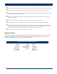
AIR SUPPLY • • The rivet tool is powered by compressed air at an optimum pressure of 5.5 bar (80 psi) The use of a pressure regulator filter/lubricator unit within 3 meters of the tool is highly recommended to extend the life of the tool.
MAINTENANCE Follow the instructions below to perform annual service and replacement of seals, item numbers in parentheses refer to assembly drawing part numbers on page 8. Head Assembly Replace Seals 5, 6, 7, 9 and Return Spring 8. When seals are replaced apply a very light coating of white lithium grease to the hydraulic body and to the surface of the o-rings. Pneumatic Piston Assembly Replace 36 & 34 then proceed to oil filling procedure.
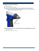
MAINTENANCE Oil Filling Procedure Turn the tool upside down. Unscrew 4 socket screws and remove air piston cover. Remove air cylinder and hydraulic piston rod until oil is exposed. Empty oil by turing the tool upside down and draining into a suitable container making best efforts to keep the tool handle and other parts from oil contamination. After oil is drained, remove excess oil from top surface. Add new oil (Mobile DTE 24 light hydraulic oil is preferred) by pouring into the hydraulic tube as shown.
MAINTENANCE Trigger Inspect trigger pin valve by insuring 56 has not come loose. The proper depth should be just under the valve stem. If adjustment is necessarym using a fork wrench or tire valve tool, screw the trigger pin 56 into the valve stem. A very small amount of loctite243 is ok around the threaded portion only. If the trigger still fails, remove the trigger pin assembly from the valve stem and inspect the seal around the trigger pin for damage. If damaged, purchase a replacement part.
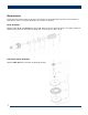
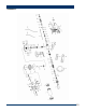
SCHEMATIC 10
PARTS LIST Index 1. 2. 3. 4. 5. 6. 7. 8. 9. 10. 12. 13. 14. 15. 16. 17. 18. 19. 20. 21. 22. 23. 24. 25. 26. 27. 28. 29. 30. 31. 32. 33. 34. 35. 36. 37. 38. 39. 40. 41. 42. 43. 44. 45. 46. 47. 48. 49. 50. 51.
OIL MATERIAL SAFETY DATA SHEET (MSDS) Priming is ALWAYS necessary after the tool has been dismantled and prior to operating. It may also be necessary to restore the full stroke after considerable use, when the stroke may be reduced and fasteners are not fully placed by one operation of the trigger Oil Details The recommended oil for priming is Mobil DTE 24 or Hyspin VG32 available in 0.51 or one gallon containers, or, you can use 30W hydraulic oil. Please see safety data below.
TROUBLESHOOTING Item numbers in parentheses refer to assembly drawing part numbers on page 9.
Warranty Statement: Industrial Rivet & Fastener Co. Inc. and Zipp Tools (hereinafter “IRF”), hereby warrants to the initial retail customer and original distributor (“Warrantee”) only that its products will be free from defects in material and workmanship for a period of 1 year from the purchase date, provided that the products are used in accordance with “IRF’s” instructions as to maintenance, operation and use.