
User's Manual


www.airkinglimited.com
5S7635037 New 10-06 4 of 16
SECTION 6
Ducting
CAUTION: ALL DUCTING MUST COMPLY WITH LOCAL AND
NATIONAL BUILDING CODES.
NOTE: Insulated ducting is required for bathroom exhaust applications,
where ducting passes through unconditioned space or where noise
is a factor. Failure to use insulation could result in excessive
condensation buildup within the duct, and undesirable sound levels
within the room. Duct runs should have as few bends as possible.
NOTE: Flexible insulated ducting may be used where allowed by local
code. For the quietest possible installations, it is recommended a
minimum of 8' of insulated flexduct be used between any exhaust grill
and fan. When using flexible type duct work, duct should be stretched
as tight and straight as possible. Failure to do so could result in
dramatic loss of system performance. Flexible duct should be
connected to the fan with screw clamps or duct tape. All connections
should be as airtight as possible to maximize system performance.
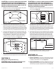
1. Connect one end of the ducting (not included) to the room
level grill housing and the other end to the “Y” transition.
Secure both ends in place using tape or a screw clamp to
create as air tight a seal as possible. Repeat this step for the
other room level grill housing (Figure 11).
NOTE: Units that include only one collar do not utilize the “Y”
transition. Follow the same instructions as in step 1, except
connect the one end of the ducting directly to the fan.
2. Connect one end of the ducting to the top of the “Y” transition
and the other end to the intake of the fan (Figure 11).
3. Connect one end of the ducting to the exhaust of the fan and
the other end to a wall or ceiling cap. (Figure 11). Always
duct the fan to the outside through a wall or roof cap.
NOTE: When using insulated flexible duct, it is recommended that
the inner vinyl core be screw clamped or taped to the inlet and
outlet and that the vapor barrier surrounding the insulation be
taped to the fan housing.
NOTE: When attaching flex duct to the collar/damper combination
and an immediate elbow is necessary, be certain that the elbow is
installed with a "soft" bend to allow damper blades to operate properly.
SECTION 7
Installing Optional Balancing Damper
Some kits include an optional balancing damper to allow for
adjustment of the system. The damper may be used where the
grills will be connected using branches of unequal length or
where the flow will need to be balanced for any reason. To Install
the optional damper:
1. The damper must be installed on the branch with the least
restriction. This is generally the duct that is shortest or has
the fewest bends.
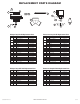
2. Drill a 5/16" hole approximately 1-1/2" from the edge on the
flat side of the “Y” transition.
3. Insert the shaft of the damper into the hole drilled in step 2. Place
the washer, handle, then wing nut onto the shaft (Figure 12).
4. Adjust the damper to balance airflow and tighten the wing
nut to secure.
SECTION 8
Wiring the Fan
CAUTION: MAKE SURE POWER IS SWITCHED OFF AT
SERVICE PANEL BEFORE STARTING INSTALLATION.
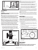
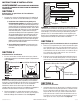
Figure 10
Ceiling
Housing Grill Collar
Housing
Joist
Figure 11
Exhaust to
Wall/Roof Cap
Fan
“Y” Transition
Grill Housing
Ducting
Figure 12
Damper
“Y” Transition
Hole
Wing Nut
Handle
Washer
Shaft