
Product Manual


NOTE: If the fan motor plug is
connected to the fan housing
receptacle, unplug so the
blower assembly can be
completely removed.
2. Run wiring from an approved wall switch carrying the appropriate rating. One neutral
(White), one ground (green or bare copper), and three hot (Black, Red, Yellow leads
connected to the switch, one for each function). Secure the electrical wires to the
housing with an approved electrical connector. Make sure you leave enough wiring in the
box to make the connection to the fan’s receptacle.
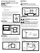
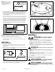
3. From where you have chosen to access the fan’s junction box, connect the White wire
from the house to the two White wires from the fan. Connect one Hot (Black) wire from
the wall switch to the Black wire from the fan (this is the fan control). Connect second Hot
(Red) wire from the wall switch to the Red wire from the fan (this is the night light control).
Connect the third Hot (Yellow) wire from the wall switch to the Yellow wire from the fan (this
is the main light control). Connect the ground wire (green or bare copper) from the house to
the Green wire from the fan (Figure 8). Use approved methods for all connections.
NOTE: The fan’s receptacle wires might need to be pulled outside compartment for connection.
Only pull the three loose wires outside of compartment. Additional wires will be present.
4. Carefully tuck wires back inside wire compartment and replace wire compartment cover
securing with the screw that was removed earlier.
SECTION 6
Completing the Installation
1. If the fan’s blower assembly was removed during the wiring process, reinstall the blower
by reversing the directions in Step 1b in Section 5 Wiring.
2. Plug the fan’s quick connect motor cord into the receptacle. This cord will only fit one
way into the receptacle (Figure 9).
3. Install a 100 watt maximum, type A19 medium base incandescent bulb (not included).
Install a 7 watt maximum type C7 (candelabra base) night light (not included) into the
side lamp holder (Figure 10).
www.airkinglimited.com
210952012 Rev. H 4-16 3 of 12
4. Install the grill by squeezing the two ends of the springs together and installing them up
into the slots on the fan’s housing. Push the grill up into position (Figure 11).
5. Restore power and test your installation.
SECTION 7
Use and Care
CAUTION: MAKE SURE POWER IS SWITCHED OFF AT
SERVICE PANEL BEFORE STARTING INSTALLATION.
1. Cleaning the Grill: Remove grill and use a mild detergent, such as dishwashing liquid,
and dry with a soft cloth. NEVER USE ANY ABRASIVE PADS OR SCOURING POWDERS.
Completely dry grill before reinstalling. Refer to instructions in Section 6 Finishing the
Installation, to reinstall grill.
2. Cleaning the Fan Assembly: Wipe all parts with a dry cloth or gently vacuum the fan.
NEVER IMMERSE ELECTRICAL PARTS IN WATER.
CAUTION: ALLOW BULBS TO COOL BEFORE REPLACING.
3. Changing the Lamp: Disconnect power to the unit. Remove grill by pulling downward on
grill and squeezing grill springs together to release from housing (Figure 11).
Bulb: Unscrew bulb from lamp holder and replace with a 100 watt maximum, type A19
medium base incandescent bulb.
Night Light: Unscrew night light bulb from socket and replace with a 7 watt maximum type
C7 (candelabra base) night light bulb.
CALIFORNIA RESIDENTS ONLY:
WARNING: THIS PRODUCT CAN EXPOSE YOU TO A CHEMICAL [OR
CHEMICALS] KNOWN TO THE STATE OF CALIFORNIA TO CAUSE CANCER.
WARNING: THIS PRODUCT CAN EXPOSE YOU TO A CHEMICAL
[OR CHEMICALS] KNOWN TO THE STATE OF CALIFORNIA TO CAUSE
REPRODUCTIVE TOXICITY.
Figure 7
Screw
Wire
Compartment
Cover
Figure 11
Figure 9
Figure 10
Lamp
Lamp Holder
Night Light
Figure 8
Supply from house
Neutral (White)
Ground (Green or Bare)
Fan
Neutral (White)
Green
Hot (Black)
Yellow
Red
Black