
Use & Care Guide

SECTION 4
Wiring
CAUTION: MAKE SURE POWER IS SWITCHED OFF AT SERVICE
PANEL BEFORE STARTING INSTALLATION.
CAUTION: ALL ELECTRICAL CONNECTIONS MUST BE MADE
IN ACCORDANCE WITH LOCAL CODES, ORDINANCES, OR NATIONAL
ELECTRICAL CODE. IF YOU ARE UNFAMILIAR WITH METHODS OF
INSTALLING ELECTRICAL WIRING, SECURE THE SERVICES OF A
QUALIFIED ELECTRICIAN.
NOTE: This unit includes a side access panel for wiring that does not
require the removal of the fan’s blower assembly. If you choose to wire
the unit from the inside, you will need to remove the blower assembly
and internal wiring compartment. Both methods are equally effective.
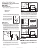
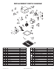
1a. External Wire Compartment: Remove the wire compartment cover
screw and place cover in a secure place (Figure 7).
1b. Internal Wire Compartment: Using a 7/16" socket, remove the two
hex nuts holding the blower assembly in place. Lift up on the
assembly and slide it out of the tabs on the housing (Figure 8).
Remove the wire compartment cover screw and place the cover
in a secure place (Figure 9).
NOTE: If the fan motor plug is connected to the fan housing receptacle,
unplug so the blower assembly can be completely removed.
2. Run wiring from an approved wall switch carrying the appropriate
rating. One neutral (white), one ground (green or bare copper), and
one hot (black lead connected to the switch). Secure the electrical
wires to the housing with an approved electrical connector. Make
sure you leave enough wiring in the box to make the connection
to the fan’s receptacle.
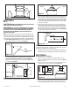
3. From where you have chosen to access the fan’s junction box,
connect the white wire from the house to the white wire from the
fan’s receptacle. Connect the black wire from the wall switch to
the black wire from the fan’s receptacle. Connect the ground wire
from the house to the green wire from the fan housing (Figure 10).
Use approved methods for all connections.
NOTE: The fan’s receptacle wires might need to be pulled outside
compartment for connection. Only pull the three loose wires outside of
compartment. Additional wires will be present.
4. Carefully tuck wire back inside wire compartment and replace wire
compartment cover securing with the screw that was removed earlier.
SECTION 5
Completing the Installation
1. If the fan’s blower assembly was removed during the wiring
process, reinstall the blower by reversing the directions in Section
4 (Wiring)
, Step 1b
.
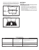
2. Plug the fan’s quick connect motor cord into the receptacle. This
cord will only fit one way into the receptacle (Figure 11).
3. Install the ceiling mounting flange to cover any gaps which exist
between the housing and the finished ceiling. Line up the slots in
the ceiling mounting flange with the screws on the inside of the
www.airkinglimited.com
3 of 12
Figure 7
Screw
Wire
Compartment
Cover
Figure 8
Plug
Hex Nuts
Tabs
Ground
Hot (Black)
White
Supply from
house
Figure 11
Ducting
Duct
Collar
Figure 6
Screw
Wire Compartment
Cover
Figure 9
Figure 10
210572051 Rev. A 8-05