
Installation Guide


INSTALLATION INSTRUCTIONS
CAUTION: MAKE SURE POWER IS SWITCHED OFF AT
SERVICE PANEL BEFORE STARTING INSTALLATION.
SECTION 1
Preparing the Exhaust Fan
1. Unpack fan from the carton and confirm that all pieces are present. In addition to the
exhaust fan you should have:
1 - Grill
1 - Damper Assembly (attached)
2 - Mounting Brackets (attached)
1 - Instruction/Safety Sheet
2. Choose the location for your fan. To ensure the best air and sound performance, it is
recommended that the length of ducting and the number of elbows be kept to a minimum,
the radius of each elbow be as large as possible for the
installation, and that insulated hard ducting be used.
This fan will require at least 12" of clearance in the
ceiling or wall, and will mount through drywall up to
½" thick. The fan mounts between 24" on center joists
using the provided mounting brackets.
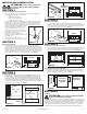
3. Select the most convenient electrical knockout and
remove using a straight-blade screw driver (Figure 1).
4. No additional vibration deadening materials are needed
or this fan.
SECTION 2
New Construction
1. If the mounting brackets are not already in place, install both brackets through the top
set of slots on the fan housing and secure in place with the four included nuts as shown.
Center the fan housing between the joists and secure the mounting brackets with screws
(not included) to the joist. Adjust the height of the housing so that it will be flush with the
finished ceiling by loosening the mounting bracket nuts and sliding the housing up or
down on the bracket. Full tighten all four nuts to secure the housing in place (Figure 2).
SECTION 3
Existing Construction
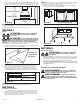
1. Install two - 2 x 4 headers (not included) between the joists (Figure 3). Install the
mounting brackets through the top set of slots on the fan housing and secure in place
with the four included nuts. Position the fan housing between the headers and secure
the mounting brackets with screws (not included) to the header. Adjust the height of the
housing so that it is flush with the finished ceiling by loosening the mounting bracket
nuts and sliding the housing up or down on the bracket. Fully tighten all four nuts to
secure the housing in place (Figure 4).
www.airkinglimited.com
6728051 Rev. G 3-16 2 of 8
SECTION 4
Hanging Installation
1. If the mounting brackets are not already in place, install both brackets through the top
set of slots on the fan housing and secure in place with the four included nuts as shown.
Lift unit up onto the threaded rods and secure in place using appropriate hardware (not
included) (Figure 5).
SECTION 5
Converting to vertical discharge
1. To convert unit for vertical discharge, remove 9 screws holding the side access panel
in place. Turn unit 90° and reinstall panel. Make sure the grill screw hole in the panel is
facing up (Figure 6).
Converting for Inline Usage
2. Determine if you will require the unit to exhaust vertically/horizontally or at a right angle
and install the optional IA418RE duct adapter panel (not included) accordingly, using the
included screws (Figure 7).
SECTION 6
Ducting
CAUTION: ALL DUCTING MUST COMPLY WITH LOCAL AND
NATIONAL BUILDING CODES.
NOTE: The ducting from this fan to the outside of the building has a strong effect on the air
flow, noise and energy use of the fan. Use the shortest, straightest duct routing possible
for best performance, and avoid installing the fan with smaller ducts than recommended.
Insulation around the ducts can reduce energy loss and inhibit mold growth. Fans installed
with existing ducts may not achieve their rated air flow.
Figure 3
Joist
2 x 4 Header
2 x 4 Header
Joist
Ceiling
Bracket
Header
Figure 4
Side Discharge
Figure 6
Vertical Discharge
Figure 1
Figure 2
Bracket
Housing
Nut
Joist
Figure 5
Bracket
Housing
Nut
Threaded Rod
Right Angle
Discharge
Horizontal/
Vertical
Discharge
Figure 7
Duct
Apapter
Screws