
Installation Guide


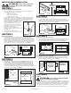


1. Connect the ducting to the fan’s duct collar (Figure 8). Secure in place using duct tape.
Always duct the fan to the outside through a wall or roof cap. It is recommended that
low restriction termination fittings be used.
NOTE: To transition to round ducting, Air King recommends using model OA10H 4½" x 18" to 10"
round transition (not included). When using model OA10H, the existing duct collar must be removed.
SECTION 7
Wiring
CAUTION: MAKE SURE POWER IS SWITCHED OFF AT
SERVICE PANEL BEFORE STARTING INSTALLATION.
CAUTION: ALL ELECTRICAL CONNECTIONS MUST BE
MADE IN ACCORDANCE WITH LOCAL CODES, ORDINANCES, OR
NATIONAL ELECTRICAL CODE. IF YOU ARE UNFAMILIAR WITH METHODS OF INSTALLING
ELECTRICAL WIRING, SECURE THE SERVICES OF A QUALIFIED ELECTRICIAN.
NOTE: This unit includes a side access panel for wiring that does not require the removal of the
fan’s blower assembly.
1. Remove the wire compartment cover screw and place cover in a secure place (Figure 9).
2. Pull the loose black, white and green wires out from the wire compartment (additional
wires will be present). Install an approved electrical connector (not included) to the wire
compartment cover. Run a black (hot), white (neutral), and a green or bare ground wire
from the supply. Connect all wires from the supply to their corresponding wires within the
wire compartment (Figure 10). Use approved methods for all connections.
3. Carefully tuck wire back inside wire compartment and replace wire compartment cover
securing with the screw that was removed earlier.
SECTION 8
Completing the Installation
1. Use a sealant appropriate for contact with the building materials present and for the
temperature requirements of the installation to prevent air leakage from unconditioned
spaces is recommended. If gaps between unit housing and ceiling are great, additional
material (backing rod, ceiling material) may be required.
NOTE: This fan is rated for direct insulation contact (Type IC) and it is recommended that this fan
be completely covered by insulation in order to reduce heat loss or gain to unconditioned space.
www.airkinglimited.com
6728051 Rev. G 3-16 3 of 8
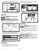
2. Confirm that all wire harness’s coming from the blowers are plugged into their
receptacles on the mounting channel (Figure 11).
3. Install the grill with the four (4) included mounting screws (Figure 12).
4. Restore power and test your installation.
SECTION 9
Use and Care
CAUTION: MAKE SURE POWER IS SWITCHED OFF AT
SERVICE PANEL BEFORE SERVICING THE UNIT.
1. Cleaning the Grill: Remove grill and use a mild detergent, such as dishwashing liquid,
and dry with a soft cloth. NEVER USE ANY ABRASIVE PADS OR SCOURING POWDERS.
Completely dry grill before reinstalling. Refer to instructions in Section 8 Completing the
Installation, to reinstall grill.
2. Cleaning the Fan Assembly: Wipe all parts with a dry cloth or gently vacuum the fan.
NEVER IMMERSE ELECTRICAL PARTS IN WATER.
CALIFORNIA RESIDENTS ONLY:
WARNING: THIS PRODUCT CAN EXPOSE YOU TO A CHEMICAL [OR
CHEMICALS] KNOWN TO THE STATE OF CALIFORNIA TO CAUSE CANCER.
WARNING: THIS PRODUCT CAN EXPOSE YOU TO A CHEMICAL
[OR CHEMICALS] KNOWN TO THE STATE OF CALIFORNIA TO CAUSE
REPRODUCTIVE TOXICITY.
Figure 8
Housing
Ducting
Duct Collar
Optional Transition
Figure 12
Figure 9
Screw
Wire
Compartment
Cover
Figure 11
Wire Harness
Figure 10
Supply from house
Black
Neutral (White)
Ground (Green or Bare)
Fan
Neutral (White)
Green
Black