
Exhaust Fan Operating Manual

the junction box. The neutral (white) wire from the home is not
connected to the switch or junction box, but will be run to the unit’s
wire compartment. Use approved methods for all connections.
2. Run wiring from wall switches carrying the appropriate rating. One
neutral (white), one ground (green or bare copper), and four hot
(black, red, blue, yellow leads connected to the switch, one for
each function). Secure the electrical wires to the housing with an
approved electrical connector. Make sure you leave enough wiring
in the box to make the connection to the fan’s receptacles.
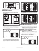
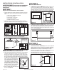
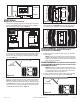
3. Connect the white wire from the house to the four white wires from
the fan. Connect one hot (black) wire from the wall switch to the
black wire from the fan (this is the fan control). Connect second
hot (red) wire from the wall switch to the red wire from the fan (this
is the heat control). Connect the third hot (blue) wire from the wall
switch to the blue wire from the fan (this is the main light control).
Connect the fourth hot (yellow) wire from the wall switch to the
yellow wire from the fan (this is the night light control). Connect
the ground wire from the house to the green wire from the fan
(Figure 9). Use approved methods for all connections.
4. Reinstall the wire compartment cover by sliding the tabs at the
bottom of the cover into the slots in the housing. Make sure all
wires are tucked inside of the compartment and are not being
pinched or showing through. Reinstall the two screws removed in
Step 3 of SECTION 1
Preparing the Unit
(Figure 10).
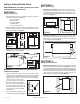
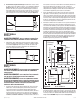
1a. Mounting Tab Installation: Position housing against the joist and
trace an outline of the housing onto the ceiling material (Figure 7).
Set housing aside and cut opening, being careful not to cut or
damage any electrical or other hidden utilities. Place housing next
to the joist and insure that it is flush with the finished ceiling. Secure
with screws or nails (not provided) to the joists (Figure 5).
SECTION 4
Ducting
CAUTION: ALL DUCTING MUST COMPLY WITH LOCAL AND
NATIONAL BUILDING CODES.
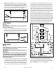
1. Remove any tape that might be holding the damper in place during
shipping and connect the ducting to the fan’s duct collar (Figure
8). Secure in place using tape or screw clamp. Always duct the
fan to the outside through a wall or roof cap.
SECTION 5
Wiring
CAUTION: MAKE SURE POWER IS SWITCHED OFF AT SERVICE
PANEL BEFORE STARTING INSTALLATION.
WARNING: THIS UNIT MUST BE WIRED ON A SEPARATE 20
AMP CIRCUIT.
CAUTION: ALL ELECTRICAL CONNECTIONS MUST BE MADE
IN ACCORDANCE WITH LOCAL CODES, ORDINANCES, OR NATIONAL
ELECTRICAL CODE. IF YOU ARE UNFAMILIAR WITH METHODS OF
INSTALLING ELECTRICAL WIRING, SECURE THE SERVICES OF A
QUALIFIED ELECTRICIAN.
1. Using wiring carrying the appropriate rating, run a dedicated line
on a 20 amp service from the main service panel to an approved
wall junction box (not included). Once inside the junction box, split
the hot (black) wire from the home and connect one end to each
of the switches into the terminal marked “COMMON TERMINAL”.
Connect the ground (green or bare copper) wire from the home to
www.airkinglimited.com
965 Rev. A 9-05 3 of 12
Figure 7
Figure 8
Figure 9
Ground
Hot (Black)
Supply from house
White
Hot (Yellow)
Hot (Blue)
Hot (Black)
Hot (Red)
SwitchSwitch