
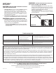
Troubleshooting guide


SECTION 6
Completing the Installation
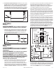
1. Insert the plug from the heating unit into the receptacle marked
“HEAT”, and the plug from the fan into the receptacle marked
“VENT”(Figure 11).
2. Remove grill from carton and open light lens area by pushing in on
the two tabs of the light lens and pulling outward from lens. The
lens will swing open on the connector bars. DO NOT remove the
lens from the grill (Figure 12).
3. Install light reflector into grill by lining up the posts on grill with the
holes in light reflector (Figure 13). Raise light reflector and grill up
to housing and insert plug from light into receptacle marked “LIGHT”
(located on the side of the wire compartment) and insert plug from
night light into receptacle marked “NIGHT LIGHT” (Figure 11).
www.airkinglimited.com
965 Rev. A 9-05 4 of 12
4. Attach light reflector in place with the two screws removed during
Step 2
in SECTION 1
Preparing the Unit
so grill fits snuggly against
ceiling (Figure 14).
CAUTION: FAILURE TO SECURE THE REFLECTOR SCREWS MAY
RESULT IN A RATTLING OR HUMMING NOISE.
5. Install the appropriate bulbs (not included) specific to your model:
AK965L: Install a 100 watt maximum, type A19 medium base
incandescent bulb (not included) and a 7 watt maximum type
C7 (candelabra base) night light (not included).
WARNING: TO REDUCE THE RISK OF FIRE, USE ONLY TYPE
G24-d3, QUAD 2-PIN LAMP, 26 WATT MAXIMUM.
AK965FL: Install a high efficacy 26 watt maximum, 2 pin quad,
G24-d3 fluorescent bulb (not included) and a 7 watt maximum
type C7 (candelabra base) night light (not included).
6. Close the light lens and secure in place by swinging back into
position and snapping the tabs in place (Figure 15).
7. Restore power and test your installation.
Figure 10
Tab
Slot
Figure 11
Heater
Vent
Figure 12
Tabs
Connector Bar
Figure 13
Hole
Post
Post
Figure 14
Screws
Figure 15
Tabs
Connector Bar
Light