DMO2420 Microwave Parts and Service Manual
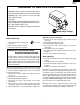
DMO2420B DMO2420R DMO2420S WARNING TO SERVICE PERSONNEL Microwave ovens contain circuitry capable of producing very high voltage and current, contact with following parts may result in a severe, possibly fatal, electrical shock. (Example) High Voltage Capacitor, High Voltage Power Transformer, Magnetron, High Voltage Rectifier Assembly, High Voltage Harness etc.. Read the Service Manual carefully and follow all instructions. Don't Touch ! Danger High Voltage When the testing is completed, 1.
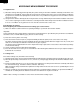
DMO2420B DMO2420R DMO2420S MICROWAVE MEASUREMENT PROCEDURE A. Requirements: 1) Microwave leakage limit (Power density limit): The power density of microwave radiation emitted by a microwave oven should not exceed 1mW/cm2 at any point 5cm or more from the external surface of the oven, measured prior to acquisition by a purchaser, and thereafter (through the useful life of the oven), 5 mW/cm2 at any point 5cm or more from the external surface of the oven.
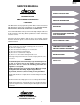
DMO2420B DMO2420R DMO2420S SERVICE MANUAL distinctive appliances PRODUCT DESCRIPTION MICROWAVE OVEN DMO2420B/DMO2420R/DMO2420S GENERAL INFORMATION FOREWORD This Manual has been prepared to provide Dacor Service Personnel with Operation and Service Information for the DACOR MICROWAVE OVENS, DMO2420B, DMO2420R and DMO2420S. OPERATION It is recommended that service personnel carefully study the entire text of this manual so that they will be qualified to render satisfactory customer service.
DMO2420B DMO2420R DMO2420S SPECIFICATION ITEM DESCRIPTION Power Requirements 120 Volts / 13.8 Amperes 60 Hertz Single phase, 3 wire grounded Power Output 1200 watts (IEC TEST PROCEDURE) Operating frequency of 2450MHz Case Dimensions Width 24" Height 13-3/8" Depth 19-1/8" Cooking Cavity Dimensions Width 17-3/8" Height 10-1/2" Depth 18-5/8" 2.0 Cubic Feet Control Complement Touch Control System Clock ( 1:00 - 12:59 ) Timer (0 - 99 min.
DMO2420B DMO2420R DMO2420S Where a two-pronged wall-receptacle is encountered, it is the personal responsibility and obligation of the customer to contact a qualified electrician and have it replaced with a properly grounded three-pronged wall receptacle or have a grounding adapter properly grounded and polarized. If the extension cord must be used, it should be a 3-wire, 15 amp. or higher rated cord.
DMO2420B DMO2420R DMO2420S OPERATION DESCRIPTION OF OPERATING SEQUENCE the secondary interlock switch and primary interlock relay and is mechanically associated with the door so that it will function in the following sequence. (1) When the door opens from the closed position, the primary interlock relay (RY2) and secondary interlock switch open their contacts. And contacts of the relay (RY1) remains closed. Then the monitor switch contacts close.
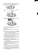
DMO2420B DMO2420R DMO2420S The time of supplementary cooking is determined by experiment with each food category and inputted into the LSI. An example of how sensor works: (POTATOES) 1. Potatoes at room temperature. Vapor is emitted very MIC RO WA slowly. VE 2. Heat Potatoes. Moisture and humidity is emitted rapidly. You can smell the aroma asMitICcooks. AH SENSOR RO WA VE 3. Sensor detects moisture and humidity and calculates cooking time and variable power. Cooking Sequence. 1.
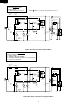
DMO2420B DMO2420R DMO2420S SCHEMATIC NOTE: CONDITION OF OVEN 1. DOOR CLOSED. 2. CLOCK APPEARS ON DISPLAY. MAGNETRON TEMP. FUSE NOTE: Indicates components with potential above 250 V. MONITOR FUSE 20A COM. N.O. CAPACITOR 1.0µF AC 2300V F1 AH SENSOR (RY-2) PRIMARY INTERLOCK RELAY (RY-1) A1 F2 F3 A2 GRN CONTROL UNIT N.O. COM. 120V AC 60 Hz B1 POWER TRANSFORMER B2 N.C. DOOR SENSING SWITCH CAVITY TEMP. FUSE TTM OL OVEN LAMP MONITOR SWITCH FM TURNTABLE MOTOR COM. H.V.
DMO2420B DMO2420R DMO2420S DESCRIPTION AND FUNCTION OF COMPONENTS DOOR OPEN MECHANISM open, the monitor fuse blows simultaneously with closing of the monitor switch contacts. CAUTION: BEFORE REPLACING A BLOWN MONITOR FUSE TEST THE DOOR SENSING SWITCH, PRIMARY INTERLOCK RELAY (RY2), RELAY (RY1), SECONDARY INTERLOCK SWITCH AND MONITOR SWITCH FOR PROPER OPERATION. (REFER TO CHAPTER "TEST PROCEDURE"). NOTE: MONITOR FUSE AND MONITOR SWITCH ARE REPLACED AS AN ASSEMBLY.
DMO2420B DMO2420R DMO2420S TROUBLESHOOTING GUIDE Never touch any part in the circuit with your hand or an uninsulated tool while the power supply is connected. When troubleshooting the microwave oven, it is helpful to follow the Sequence of Operation in performing the checks. Many of the possible causes of trouble will require that a specific test be performed. These tests are given a procedure letter which will be found in the "Test Procedure "section.
DMO2420B DMO2420R DMO2420S CK = Check / RE = Replace POSSIBLE CAUSE AND DEFECTIVE PARTS CONDITION PROBLEM RE RE A B C D E E F F G H RE RE CK I CK CK CK J K L M N SHORT IN POWER CORD SHORT OR OPENED WIRING MAGNETRON POWER TRANSFORMER H.V.
DMO2420B DMO2420R DMO2420S TEST PROCEDURES PROCEDURE LETTER A COMPONENT TEST MAGNETRON ASSEMBLY TEST 1. 2. 3. 4. 5. 6. 7. 8. 9. Disconnect the power supply cord, and then remove outer case. Open the door and block it open. Discharge high voltage capacitor. To test for an open filament, isolate the magnetron from the high voltage circuit. A continuity check across the magnetron filament leads should indicate less than 1 ohm.
DMO2420B DMO2420R DMO2420S TEST PROCEDURES PROCEDURE LETTER COMPONENT TEST (HIGH VOLTAGES ARE PRESENT AT THE HIGH VOLTAGE TERMINAL, SO DO NOT ATTEMPT TO MEASURE THE FILAMENT AND HIGH VOLTAGE.) C HIGH VOLTAGE RECTIFIER TEST 1. 2. 3. 4. Disconnect the power supply cord, and then remove outer case. Open the door and block it open. Discharge high voltage capacitor. Isolate the rectifier from the circuit.
DMO2420B DMO2420R DMO2420S TEST PROCEDURES PROCEDURE LETTER COMPONENT TEST 5. Reconnect all leads removed from components during testing. 6. Reinstall the outer case (cabinet). 7. Reconnect the power supply cord after the outer case is installed. 8. Run the oven and check all functions. CAUTION: IF THE TEMPERATURE FUSE INDICATES AN OPEN CIRCUIT AT ROOM TEMPERATURE, REPLACE TEMPERATURE FUSE. F SECONDARY INTERLOCK SWITCH TEST 1. 2. 3. 4. 5. 6. 7. 8.
DMO2420B DMO2420R DMO2420S TEST PROCEDURES PROCEDURE LETTER COMPONENT TEST 5. 6. 7. 8. with the door opened (in this condition the plunger of the monitor switch is pushed in), the meter should indicate an open circuit. If improper operation is indicated, the switch may be defective. After testing the monitor switch, reconnect the wire lead to the monitor switch (COM) terminal and check the continuity of the monitor circuit. Reconnect all leads removed from components during testing.
DMO2420B DMO2420R DMO2420S TEST PROCEDURES PROCEDURE LETTER COMPONENT TEST 4) Reconnect the power supply cord after the outer case is installed. 5) Run the oven and check all functions. The following symptoms indicate a defective key unit. a) When touching the pads, a certain pad produces no signal at all. b) When touching a number pad, two figures or more are displayed. c) When touching the pads, sometimes a pad produces no signal. If the Key unit is defective.
DMO2420B DMO2420R DMO2420S TEST PROCEDURES PROCEDURE LETTER COMPONENT TEST 5. 6. 7. 8. may be used (after clearing the control unit) to determine if the control unit or key pad is at fault. Reconnect all leads removed from components during testing. Re-install the outer case (cabinet). Reconnect the power supply cord after the outer case is installed. Run the oven and check all functions.
DMO2420B DMO2420R DMO2420S TEST PROCEDURES PROCEDURE LETTER COMPONENT TEST MENU Steaks, chops or fish 0.5lb 1ST STAGE LEVEL TIME 70% 30sec. 2ND STAGE LEVEL TIME 40% 15sec. (5) If improper operation is indicated, the control unit is probably defective and should be checked. M FOIL PATTERN ON THE PRINTED WIRING BOARD TEST To protect the electronic circuits, this model is provided with a fine foil pattern added to the primary on the PWB, this foil pattern acts as a fuse. 1.
DMO2420B DMO2420R DMO2420S TEST PROCEDURES PROCEDURE LETTER COMPONENT TEST 10) Discharge high voltage capacitor. 11) Reconnect all leads removed from components during testing. 12) Re-install the outer case (cabinet). 13) Reconnect the power supply cord after the outer case is installed. 14) Run the oven and check all functions. N AH SENSOR TEST Checking the initial sensor cooking condition WARNING : The oven should be fully assembled before following procedure.
DMO2420B DMO2420R DMO2420S TEST PROCEDURES PROCEDURE LETTER COMPONENT TEST 9-3. Close the door. 9-4. Touch the Timer/Clock pad once, the Power Level pad twice, the Start pad once and the number pad 1 once. 9-5. The control panel is in automatic Sensor operation. 9-6. And then the oven will turn off automatically, and the time for detecting moisture will be displayed. If new sensor dose not operate properly, the problem is with the control unit, and refer to explanation below.
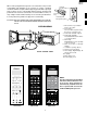
DMO2420B DMO2420R DMO2420S TOUCH CONTROL PANEL ASSEMBLY OUTLINE OF TOUCH CONTROL PANEL 4) Relay Circuit A circuit to drive the magnetron, fan motor, turntable motor and light the oven lamp. The touch control section consists of the following units. (1) Key Unit (2) Control Unit (The Control Unit consists of Power Unit and LSI Unit). 5) Buzzer Circuit The buzzer is responsive to signals from the LSI to emit audible sounds (key touch sound and completion sound).
DMO2420B DMO2420R DMO2420S LSI(IXA098DR) The I/O signal of the LSI(IXA098DR) is detailed in the following table. Pin No. Signal I/O Description 1 COM5 OUT Common data signal : COM11. Connected to LCD signal COM11. 2 COM4 OUT Common data signal : COM12. Connected to LCD signal COM12. 3 COM3 OUT Common data signal : COM13. Connected to LCD signal COM13. 4 COM2 OUT Common data signal : COM14. Connected to LCD signal COM14. 5 COM1 OUT Common data signal : COM15.
DMO2420B DMO2420R DMO2420S Pin No. 34 Signal INT0 I/O IN Description Signal synchronized with commercial power source frequency. This is the basic timing for time processing of LSI. H : GND L : -5V 16.7 msec. 35 P07 OUT Key strobe signal. Signal applied to touch-key section. A pulse signal is input to AIN7, P14, P15, P16 and P17 terminal while one of G1 line keys on key matrix is touched. 36 P06 OUT Key strobe signal. Signal applied to touch-key section.
DMO2420B DMO2420R DMO2420S Pin No. Signal NC I/O _ 52 Description Terminal not used. 53 XCOUT OUT Terminal not used. 54 XCIN Connected to VC. 55 NC IN _ 56 VCC IN Power source voltage: GND(0V). The power source voltage to drive LSI is input to VCC terminal. 57 OSCSEL IN Connected to VC(-5V). 58 XOUT OUT 59 VSS IN 60 NC 61 XIN IN Internal clock oscillation frequency control input setting.
DMO2420B DMO2420R DMO2420S Pin No. Signal I/O Description 143 COM7 OUT Common data signal : COM9. Connected to LCD signal COM9. 144 COM6 OUT Common data signal : COM10. Connected to LCD signal COM10. ABSOLUTE HUMIDITY SENSOR CIRCUIT LSI are turned on in such a way as to change the resistance values in parallel with R98 ~ R102. Changing the resistance values results in that there is the same potential at both F-3 terminal of the absolute humidity sensor and AIN4 terminal of the LSI.
DMO2420B DMO2420R DMO2420S TOUCH CONTROL PANEL SERVICING 4) Re-install the outer case (cabinet). 5) Re-connect the power supply cord after the outer case is installed. 6) Run the oven and check all functions. A. On some models, the power supply cord between the touch control panel and the oven itself is so short that the two can’t be separated. For those models, check and repair all the controls (sensor-related ones included) of the touch control panel while keeping it connected to the oven. B.
DMO2420B DMO2420R DMO2420S COMPONENT REPLACEMENT AND ADJUSTMENT PROCEDURE WARNING AGAINST HIGH VOLTAGE: Microwave ovens contain circuitry capable of producing very high voltage and current, contact with following parts may result in severe, possibly fatal, electric shock. (Example) High Voltage Capacitor, Power Transformer, Magnetron, High Voltage Rectifier Assembly, High Voltage Harness etc.. WARNING: Avoid possible exposure to microwave energy.
DMO2420B DMO2420R DMO2420S CAUTION: 1. DISCONNECT OVEN FROM POWER SUP PLY BEFORE REMOVING OUTER CASE. 2. DISCHARGE THE HIGH VOLTAGE CAPACITOR BEFORE TOUCHING ANY OVEN COMPONENTS OR WIRING. NOTE: When replacing the outer case, the 2 special Torx screws must be reinstalled in the same locations. Special screw Screw Driver (Type: TORX T20 H or GTXH20-100) POWER TRANSFORMER REMOVAL 1. Disconnect the power supply cord and then remove outer case. 2. Open the oven door and block it open. 3.
DMO2420B DMO2420R DMO2420S OVEN LAMP AND LAMP SOCKET REMOVAL 1. 2. 3. 4. 5. Disconnect the power supply cord and remove outer case. Open the door and block it open. Discharge high voltage capacitor. Remove the oven lamp from the oven lamp socket. Pull the wire leads from the oven lamp socket by pushing the terminal hole of the oven lamp socket with the small flat type screw driver. 6. Remove the oven lamp socket from the magnetron duct by turning the socket counterclockwise. 7.
DMO2420B DMO2420R DMO2420S COOLING FAN MOTOR REMOVAL CAUTION: * Do not reuse the removed fan blade because the hole (for shaft) may be larger than normal. REMOVAL 1. Disconnect the power supply cord and then remove outer case. 2. Open the door and block it open. 3. Discharge high voltage capacitor. 4. Disconnect the wire leads from the fan motor. 5. Remove the two (2) screws holding the fan motor to the oven cavity back plate. 6.
DMO2420B DMO2420R DMO2420S monitor switches are in the lower position and the door sensing switch is in the upper position. 2. Re-connect wire leads to each switch. Refer to pictorial diagram. 3. Secure latch hook (with two (2) mounting screws) to oven flange. 4. Make sure that the monitor switch is operating properly and check continuity of the monitor circuit. Refer to chapter "Test Procedure" and Adjustment procedure. DOOR SENSING SWITCH/SECONDARY INTERLOCK SWITCH AND MONITOR SWITCH ADJUSTMENT 1.
DMO2420B DMO2420R DMO2420S Note: 13.Now, door panel is free. 14.Slide latch head upward and remove it from door frame by releasing latch spring from door frame and latch head. 15.Now, latch head and latch spring are free. 16.Remove one (1) screw holding the door glass stopper to the door frame. 17.Remove door glass stopper from door frame. 18.Slide the door glass rightwards and then slide upwards to release the door glass from the tabs holding it. 19.Remove the door glass from the door frame. 20.
1 RED RED A WHT CN-F 1 BLK 2 RED 3 WHT MAGNETRON TEMP. FUSE WHT B C D E F G H 1 CAVITY TEMP. FUSE NOTE: The grounding conductor of the power supply cord has been grounded by power supply cord fixing screw. The screw must always be kept tight. RED H N WHT AH SENSOR GRY POWER SUPPLY CORD 120V 60Hz 2 2 DOOR SENSING SWITCH CONTROL PANEL N.O. PNK COM.
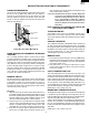
DMO2420B DMO2420R DMO2420S 2 1 4 3 6 5 A A B B CN-C 12PIN LEAD WIRE HARNESS Q2 2SB1238 R4 27 C D2 b + – D LED C2 GND C3 VC C1 VA C4 INT C9 VR C + – C4 10µ/35v D4 1SS270A C3 0.1µ/50v 6 1SS270A ZD1 HZ16-1 3 d a D1 D3 C10 R5 4.7k R1 2.4k A2 4 C2 1000µ/35v 1 A1 10G471K AC VRS1 CN-A D6 C1 0.
A B C D E F G H P20 P21 P22 R101 75kF P23 R15 4.7k (J16) COM16 COM15 COM14 COM13 COM12 COM11 COM10 COM9 SEG40 SEG39 SEG38 SEG37 SEG36 SEG35 SEG34 SEG33 SEG32 SEG31 SEG30 SEG29 SEG28 SEG27 SEG26 SEG25 SEG24 SEG23 SEG22 SEG21 SEG20 SEG19 SEG18 SEG17 SEG16 SEG15 SEG14 SEG13 SEG12 SEG11 SEG10 SEG9 SEG8 SEG7 SEG6 SEG5 SEG4 SEG3 SEG2 SEG1 COM1 COM2 COM3 COM4 COM5 COM6 COM7 COM8 R18 R17 R16 4.7k 4.7k 4.7k R19 4.7k AIN3 (J17) 4.7k (J14) AIN2 (J15) 4.7k (J10) (J12) AIN1 (J11) 4.7k 36 R40 4.
DMO2420B DMO2420R DMO2420S 2 1 4 3 6 5 A A B B (CN - C) 1 12 1 2 4 E 5 6 ZD1 R1 B Q3 SP1 1 2 7 8 9 U C SH - A R2 D5 D6 SH - B B Q2 C5 D7 VRB D 2 E Q1 B R5 R4 3 R3 D8 R6 D CN - C 1 WH - 1 C4 C 1 9 E C3 CN - B D C2 RY2 C1 10 S D4 D2 D1 T1 AC 1 VH VRS1 D3 E F P 11 E 2 XA CN - A F F (J1) D9 RY1 OMIF D U AC G (CN - D) (D10) G OL FM TTM RY3 H H Figure S-4.
Technical Service 950 S. Raymond Ave.