
Service manual

20
DMO2420B
DMO2420R
DMO2420S
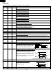
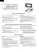
TEST PROCEDURES
PROCEDURE
LETTER
COMPONENT TEST
9-3. Close the door.
9-4. Touch the Timer/Clock pad once, the Power Level pad twice, the Start pad once and the number
pad 1 once.
9-5. The control panel is in automatic Sensor operation.
9-6. And then the oven will turn off automatically, and the time for detecting moisture will be displayed.
If new sensor dose not operate properly, the problem is with the control unit, and refer to explanation
below.
CHECKING CONTROL UNIT
(1) Disconnect the power supply cord, and then remove outer case.
(2) Open the door and block it open.
(3) Discharge high voltage capacitor.
(4) Disconnect the sensor connector that is mounted to control panel.
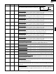
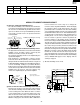
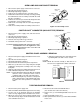
(5) Then connect the dummy resistor circuit (see fig.) to the sensor connector of control panel.
(6) Disconnect the leads to the primary of the power transformer.
(7) Ensure that these leads remain isolated from other components and oven chassis by using
insulation tape.
(8) After that procedure, re-connect the power supply cord.
(9) Check the sensor cook operation proceed as follows:
9-1. Touch the Timer/Clock pad once, the Power Level pad twice, the Start pad once and the number
pad 1 once.
9-2. The control panel is in the sensor cooking operation.
9-3. After approximately 25 seconds, push plunger of select switch for more than 3 seconds. This
condition is same as judgement by AH sensor.
9-4. After approximately 3 seconds, the oven will turn off automatically, and the display shows “ X
X . X X “ which is the time for detecting moisture.
If the above is not the case, the control unit is probably defective.
If the above is proper, the AH sensor is probably defective.
(10) Disconnect the power supply cord, and then remove outer case.
(11) Open the door and block it open.
(12) Discharge high voltage capacitor.
(13) Disconnect the dummy resistor circuit from the sensor connector of control panel.
(14) Carry out necessary repair.
(15) Reconnect all leads removed from components during testing and repairing.
(16) Re-install the outer case (cabinet).
(17) Reconnect the power supply cord after the outer case is installed. Run the oven and check all
functions.
(18) Carry out "Water load cooking test" again and ensure that the oven works properly.
R1, R2 :22
((
((
(ohm) ± 1% 1/2W
R3 :4.3k
((
((
(ohm) ± 5% 1/4W
R4 :1M
((
((
(ohm) ± 5% 1/4W
Sensor Dummy Resistor Circuit
Plunger
NC
NO
COM
COM
NO
NC
R3 R4
R1
R2
1
2
3
F-1
F-2
F-3
To connector (F)
on Control Unit.
CONNECTOR