
Service manual

23
DMO2420B
DMO2420R
DMO2420S
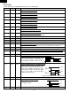
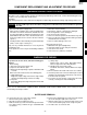
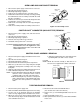
34 INT0 IN Signal synchronized with commercial power source frequency.
This is the basic timing for time processing of LSI.
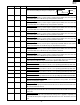
35 P07 OUT Key strobe signal.
Signal applied to touch-key section. A pulse signal is input to AIN7, P14, P15, P16 and
P17 terminal while one of G1 line keys on key matrix is touched.
36 P06 OUT Key strobe signal.
Signal applied to touch-key section. A pulse signal is input to AIN7, P14, P15, P16 and
P17 terminal while one of G2 line keys on key matrix is touched.
37 P05 OUT
Key strobe signal.
Signal applied to touch-key section. A pulse signal is input to AIN7, P14, P15, P16 and
P17 terminal while one of G3 line keys on key matrix is touched.
38 P04 OUT
Key strobe signal.
Signal applied to touch-key section. A pulse signal is input to AIN7, P14, P15, P16 and
P17 terminal while one of G4 line keys on key matrix is touched.
39 P03 OUT Key strobe signal.
Signal applied to touch-key section. A pulse signal is input to AIN7, P14, P15, P16 and
P17 terminal while one of G5 line keys on key matrix is touched.
40 P02 OUT Key strobe signal.
Signal applied to touch-key section. A pulse signal is input to AIN6, AIN7, P14, P15, P16
and P17 terminal while one of G6 line keys on key matrix is touched.
41 P01 OUT Key strobe signal.
Signal applied to touch-key section. A pulse signal is input to AIN7, P14, P15, P16 and
P17 terminal while one of G7 line keys on key matrix is touched.
42 P00 OUT Key strobe signal.
Signal applied to touch-key section. A pulse signal is input to AIN7, P14, P15, P16 and
P17 terminal while one of G8 line keys on key matrix is touched.
43 P17 OUT Signal coming from touch key.
When either G9 line on key matrix is touched, a corresponding signal out of P00-P07 will
be input into P17. When no key is touched, the signal is held at "H" level.
44 P16 IN Signal similar to P17.
When either G10 line on key matrix is touched, a corresponding signal will be input into P16.
45 P15 IN Signal similar to P17.
When either G11 line on key matrix is touched, a corresponding signal will be input into P15.
46 P14 IN Signal similar to P17.
When either G12 line on key matrix is touched, a corresponding signal will be input into P14.
47 AIN7 IN Signal similar to P17.
When either G13 line on key matrix is touched, a corresponding signal will be input into AIN7.
48 AIN6 IN Input terminal to judge the model.
The signal out of P02 will be input into AIN6 through G6 line on key matrix. The LSI will
judge the model by this signal.
49 AIN5 IN AH sensor input.
This input is an analog input terminal from the AH sensor circuit, and connected to the
A/D converter built into the LSI.
50 AIN4 IN Used for initial balancing of the bridge circuit (absolute humidity sensor). This input is an
analog input terminal from the AH sensor circuit, and connected to the A/D converter built
into the LSI.
51 RESET IN Auto clear terminal.
Signal is input to reset the LSI to the initial state when power is applied. Temporarily set
"L" level the moment power is applied, at this time the LSI is reset. Thereafter set at "H"
level
Pin No. Signal I/O Description
16.7 msec.
H : GND
L : -5V