
Service manual

28
DMO2420B
DMO2420R
DMO2420S
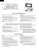
POWER TRANSFORMER REMOVAL
Reinstallation
1. Rest transformer on the bottom plate with its primary
terminals toward the oven face plate.
2.
Secure transformer with four screws to bottom plate.
3. Re-connect wire leads (primary and high voltage) to
power transformer and filament leads of transformer to
magnetron and high voltage capacitor. Refer to
"PICTORIAL DIAGRAM" on page 35.
4. Re-install outer case and check that oven is operating
properly.
1. Disconnect the power supply cord and then remove outer
case.
2. Open the oven door and block it open.
3. Discharge high voltage capacitor.
4. Disconnect wire leads (primary and high voltage) from
power transformer and the filament leads from the
magnetron and capacitor terminals.
5. Remove four (4) screws holding transformer to bottom
plate.
6. Remove transformer from bottom plate.
CAUTION: 1. DISCONNECT OVEN FROM POWER SUP
PLY BEFORE REMOVING OUTER CASE.
2. DISCHARGE THE HIGH VOLTAGE CA-
PACITOR BEFORE TOUCHING ANY OVEN
COMPONENTS OR WIRING.
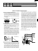
NOTE: When replacing the outer case, the 2 special
Torx screws must be reinstalled in the same
locations.
HIGH VOLTAGE RECTIFIER AND HIGH VOLTAGE CAPACITOR REMOVAL
1. Disconnect the power supply cord and then remove outer
case.
2. Open the door and block it open.
3. Discharge high voltage capacitor.
4. Disconnect the high voltage wire A from the high voltage
capacitor.
5. Disconnect the high voltage wire of high voltage rectifier
assembly from the magnetron.
6. Disconnect the filament lead (short one) of the power
transformer from the high voltage capacitor.
7. Remove one (1) screw holding capacitor holder with the
high voltage rectifier to the base plate.
8. Disconnect rectifier terminal from capacitor.
High voltage rectifier assembly is now free.
9. Remove capacitor holder. Capacitor is now free.
CAUTION: WHEN REPLACING HIGH VOLTAGE RECTI-
FIER AND HIGH VOLTAGE CAPACITOR,
GROUND SIDE TERMINAL OF THE HIGH
VOLTAGE RECTIFIER MUST BE SECURED
FIRMLY WITH A GROUNDING SCREW.
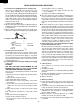
MAGNETRON REMOVAL
Removal
1. Disconnect the power supply cord and then remove outer
case.
2. Open the door and block it open.
3. Discharge high voltage capacitor.
4. Disconnect wire leads from magnetron.
5. Remove the two (2) screws holding the chassis support
to the magnetron and the oven cavity front flange.
6. Slide the magnetron duct slightly so that the two (2)
screws at left hand side of the magnetron appear.
7. Carefully remove the four (4) screws holding magnetron
to waveguide flange.
8. Remove the magnetron with care so that the magnetron
antenna is not hit by any metal object around the antenna.
9. Now, the magnetron is free.
Reinstallation
1. Re-install the magnetron to waveguide flange with care
to prevent damage to the magnetron antenna.
2. Secure the magnetron with the four (4) screws.
3. Hold the chassis support to the oven cavity front plate and
the magnetron with the two (2) screws.
4. Reconnect the wire leads to the magnetron. Refer to
"PICTORIAL DIAGRAM" on page 35.
5. Re-install outer case and check that the oven is operating
properly.
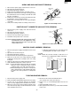
CAUTION: WHEN REPLACING MAGNETRON, BE SURE
THE R.F. GASKET IS IN PLACE AND MOUNT-
ING SCREWS ARE TIGHTENED SECURELY
S
pecial screw
Screw Driver
(Type: TORX T20 H or
GTXH20-100)