
Service manual


30
DMO2420B
DMO2420R
DMO2420S
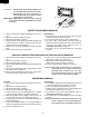
COOLING FAN MOTOR REMOVAL
REMOVAL
1. Disconnect the power supply cord and then remove outer
case.
2. Open the door and block it open.
3. Discharge high voltage capacitor.
4. Disconnect the wire leads from the fan motor.
5. Remove the two (2) screws holding the fan motor to the
oven cavity back plate.
6. Remove the fan blade from the fan motor shaft according
to the following procedure.
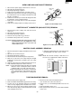
7. Hold the edge of the rotor of the fan motor by using a pair
of groove joint pliers.
CAUTION:
* Make sure that no metal pieces enter the gap between
the rotor and the stator of the fan motor because the
rotor is easily shaven by pliers and metal pieces may
be produced.
* Do not touch the pliers to the coil of the fan motor
because the coil may be cut or damaged.
* Do not disfigure the bracket by touching with the
pliers.
8. Remove the fan blade from the shaft of the fan motor by
pulling and rotating the fan blade with your hand.
9. Now, the fan blade and the fan motor will be free.
CAUTION:
* Do not reuse the removed fan blade because the hole
(for shaft) may be larger than normal.
INSTALLATION
1. Install the fan blade to the fan motor shaft according to the
following procedure.
2. Hold the center of the bracket which supports the shaft of
the fan motor on the flat table.
3. Apply the screw lock tight into the hole (for shaft) of the
fan blade.
4. Install the fan blade to the shaft of fan motor by pushing
the fan blade with a small, light weight, ball peen hammer
or rubber mallet.
CAUTION:
* Do not hit the fan blade hard when installing because
the bracket may be damaged.
* Make sure that the fan blade rotates smoothly after
installation.
* Make sure that the axis of the shaft is not slanted.
5. Install the fan motor to the the oven cavity back plate with
the two (2) screws.
6. Connect the wire leads to the fan motor, referring to the
pictorial diagram.
Side ViewRear View
1.
Disconnect the power supply cord and remove outer case.
2. Open the door and block it open.
3. Discharge high voltage capacitor.
4. Disconnect wire leads from the switches.
5.
Remove two (2) screws holding latch hook to oven flange.
6. Remove latch hook assembly from oven flange.
7. Push outward on the two (2) retaining tabs holding switch
in place.
8. Switch is now free.
At this time switch lever will be free, do not lose it.
Reinstallation
1. Re-install each switch in its place. The secondary interlock/
DOOR SENSING SWITCH/SECONDARY INTERLOCK SWITCH AND MONITOR SWITCH REMOVAL
AH SENSOR REPLACEMENT
Removal
1. Disconnect the power supply cord, and then remove
outer case.
2. Open the door and block it open.
3. Discharge high voltage capacitor.
4. Remove the two (2) screws holding the AH sensor to the
sensor duct.
5. Disconnect the AH sensor harness from the connector
CN-F on control unit.
6. AH sensor is now free.
Reinstallation
1. Insert the new AH sensor into the sensor duct.
2. Install two (2) screws to secure the AH sensor.
3. Route the AH sensor harness across the oven cavity top
plate and through the large opening.
4. Connect the AH sensor harness to CN-F on control unit.
5. Re-install the outer case cabinet and check for proper
operation.
Gap
Rotor
Bracket
Stator
Groove joint pliers
Coil
Shaft
Axis
Stator
Rotor
These are the positions
that should be pinched
with pliers
Shaft
Table
Center of
bracket