
Instruction manual
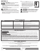
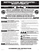

INSTALLATION INSTRUCTIONS
CAUTION: MAKE SURE POWER IS SWITCHED OFF AT
SERVICE PANEL BEFORE STARTING INSTALLATION.
SECTION 1
Preparing the Exhaust Fan
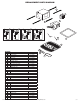
1. Unpack fan from the carton and confirm that all pieces are present. In addition to the
exhaust fan you should have:
1 - Grill
1 - Damper Assembly (attached)
4 - Mounting Rails
1 - Mounting Flange
1 - LED Lamp
1 - Instruction/Safety Sheet
2. Choose the location for your fan. To ensure the best air and sound performance, it is
recommended that the length of ducting and the number of elbows be kept to a minimum,
the radius of each elbow be as large as possible for the installation, and that insulated
hard ducting be used. Larger duct sizes will reduce noise and airflow restrictions. This
fan will require at least 10” of clearance in the ceiling or wall, and will mount through
drywall up to 3/4” thick.
3. No additional vibration deadening materials are needed for this fan.
SECTION 2
New Construction
NOTE: If the mounting flange is installed on the fan housing, remove the two screws that
connect the ceiling mounting flange to the housing and set aside (Figure 12).
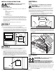
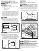
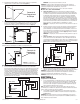
1. Install the rails into the mounting channel on the housing. Center the mounting channel in
the slots on the housing, then from inside the housing tighten the mounting channel nuts
so the channel is securely in place. Position the housing next to the joist. Line up housing
so that it will be flush with the finished ceiling. Secure the ends of the rails with screws or
nails (not included) to the joists and slide the housing into the final position (Figure 1).
SECTION 3
Existing Construction
NOTE: If the mounting flange is installed on the fan housing, remove the two screws that
connect the ceiling mounting flange to the housing and set aside (Figure 12).
1. Set housing in position between the joist and trace an outline onto the ceiling material
(Figure 2). Set housing aside and cut opening, being careful not to cut or damage any
electrical or other hidden utilities. Install the rails into the mounting channel on the
housing. Center the mounting channel in the slots on the housing, then from inside the
housing tighten the mounting channel nuts so the channel is securely in place. Position
the housing in the previously cut hole so that it is flush with the finished ceiling. Secure
the ends of the rails to the joists (Figure 1).
www.airkinglimited.com
6727902 Rev. F 6-18 2 of 12
SECTION 4
Ducting
NOTE: 6" OR LARGER RIGID DUCT IS RECOMMENDED FOR BEST PERFORMANCE.
CAUTION: ALL DUCTING MUST COMPLY WITH LOCAL AND
NATIONAL BUILDING CODES.
NOTE: The ducting from this fan to the outside of the building has a strong effect on the air
flow, noise and energy use of the fan. Use the shortest, straightest duct routing possible
for best performance, and avoid installing the fan with smaller ducts than recommended.
Insulation around the ducts can reduce energy loss and inhibit mold growth. Fans installed
with existing ducts may not achieve their rated air flow.
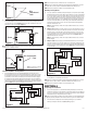
1. Connect the ducting to the fan’s duct collar (Figure 3). Secure in place using tape
or screw clamp. Always duct the fan to the outside through a wall or roof cap. It is
recommended that low restriction termination fittings be used.
2. Ensure duct joints and exterior penetrations are sealed with caulk or other similar
material to create an air-tight path to minimize building heat loss or gain and to reduce
the potential for condensation. Place/wrap insulation around duct and/or fan to in order
to minimize possible condensation buildup within the duct, as well as building heat loss
or gain (Figure 4).
SECTION 5
Wiring
CAUTION: MAKE SURE POWER IS SWITCHED OFF AT
SERVICE PANEL BEFORE STARTING INSTALLATION.
CAUTION: ALL ELECTRICAL CONNECTIONS MUST BE
MADE IN ACCORDANCE WITH LOCAL CODES, ORDINANCES, OR
NATIONAL ELECTRICAL CODE. IF YOU ARE UNFAMILIAR WITH METHODS OF INSTALLING
ELECTRICAL WIRING, SECURE THE SERVICES OF A QUALIFIED ELECTRICIAN.
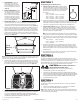
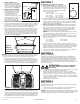
NOTE: This unit includes a side access panel for wiring that does not require the removal of the
fan’s blower assembly. If you choose to wire the unit from the inside, you will need to remove
the blower assembly and internal wiring compartment. Both methods are equally effective.
1a. External Wire Compartment: Remove the wire compartment cover screw and place
cover in a secure place (Figure 5).
Ducting
Duct
Collar
Figure 3
Figure 2
Joist
Housing
Joist
Mounting Rails
Figure 1
Figure 4
Insulation*
(place around and
over Fan Housing
Fan Housing
Power Cable*
Seal gaps
around Housing
Round
Duct*
Seal duct joints
with tape
Round
Elbows*
Wall Cap*
Roof Cap*
(with built-in
damper)
Keep duct
runs short
*Purchase separately
or