
Instruction manual
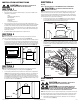
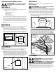
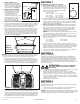

1b. Internal Wire Compartment: If the motor is already installed in the housing, remove the
two screws holding the blower assembly in place. Lift up on the assembly and slide it
out of the tabs on the housing (Figure 6). Remove the wire compartment cover screw
and place the cover in a secure place (Figure 7).
NOTE: If the fan motor plug is connected to the fan housing receptacle, unplug so the blower
assembly can be completely removed.
Standard and Motion Sensing Models
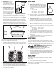
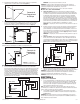
2. Connect the White wire of the fan to the White (Neutral) wire from the power source.
Connect the Black wire of the fan to the Black (Hot) wire from the power source. Connect
the ground wire from the house to the green wire from the fan housing. Using a properly
grounded three function switch (not included) connect the Black wire from the supply to
the switch. Connect the Yellow wire (fan) from the fan housing to one of the terminals on
the switch. Connect the Red wire (light) from the fan housing to a separate terminal on the
switch. Connect the Purple wire (night light) from the fan housing to a separate terminal on
the switch (Figure 8). Use approved methods for all connections.
www.airkinglimited.com
6727902 Rev. F 6-18 3 of 12
NOTE: There may be more than one white wire to be connected present.
NOTE: The fan’s receptacle wires might need to be pulled outside compartment for connection.
Only pull the five loose wires outside of compartment. Additional wires will be present.
NOTE: Unit must be grounded according to all local and national codes.
Humidity Sensing Models
3a. For proper operation the humidity sensing fan will require a 3 way switch (not included).
Run wiring between the fan and the switch location. Make sure you leave enough wiring
in each box to make the connections. At the switch box connect the black wire from the
house to the common terminal of the switch. Connect the black wire from the fan to one
of the switched terminals on the switch. This position will energize the automatic mode
and the fan will energize upon a rise in humidity. Connect the yellow wire from the fan
to the other switched terminal on the switch. This position will activate the Manual On
feature and energize the fan. Properly connect the ground and neutral (if applicable)
mount the switch and the cover.
NOTE: The yellow wire may contain a wire crimp nut which will have to be cut off and
the wire stripped.
3b. Wiring the Fan: From where you have chosen to access the fan’s junction box, connect
the white wire from the house to the white wire from the fan. Connect the wire from the
automatic position on the wall switch to the black wire from the fan, connect the wire
from the manual On position on the switch to the yellow wire from the fan. Connect the
ground wire from the house to the green wire from the fan housing (Figure 10). Use
approved methods for all connections.
NOTE: The yellow wire may contain a wire crimp nut which will have to be cut off and
the wire stripped.
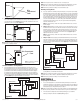
3c. Wiring the Lights: Using a properly grounded standard wall switch, connect the black
wire from the supply to one side of the switch. Connect the Red wire (light) from the fan
housing to one of the terminals on the switch. Connect the Purple wire (night light) from
the fan housing to a separate terminal on the switch. (Figure 9). Use approved methods
for all connections.
4. Carefully tuck wire back inside wire compartment and replace wire compartment cover
securing with the screw that was removed earlier.
NOTE: The fan’s receptacle wires might need to be pulled outside compartment for connection.
Only pull the five loose wires outside of compartment. Additional wires will be present.
NOTE: Unit must be grounded according to all local and national codes.
SECTION 6
Completing the Installation
1. Use a sealant appropriate for contact with the building materials present and for the
temperature requirements of the installation to prevent air leakage from unconditioned
spaces is recommended. If gaps between unit housing and ceiling are great, additional
material (backing rod, ceiling material) may be required.
NOTE: This fan is rated for direct insulation contact (Type IC) and it is recommended that this fan
be completely covered by insulation in order to reduce heat loss or gain to unconditioned space.
2. If the fan’s blower assembly was removed during the wiring process, reinstall the
blower by reversing the directions in Section 5 (Wiring), Step 1b.
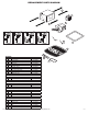
Figure 5
Screw
Wire
Compartment
Cover
Screw
Wire Compartment
Cover
Figure 7
NOTE: Wire compartment configuration
will be dependent on model.
Figure 9
Supply from house
Black
Neutral (White)
Ground (Green or Bare)
Fan
Black
Neutral (White)
Green
Switch
Black
Purple
Red
Switch
Yellow
Tabs
Screws
Figure 6
3
4
5
6
7
8
9
1
0
1
1
1
2
1
3
O
F
F
(x10)
Figure 8
Supply from house
Yellow
Neutral (White)
Ground (Green or Bare)
Fan
Neutral (White)
Green
Switch
Black
Purple
Red
Black