
Use and Care Manual


www.airkinglimited.com
6728004 Rev E 5-16 3 of 8
CAUTION: ALWAYS DUCT THE FAN TO THE OUTSIDE THROUGH A
WALL OR ROOF CAP.
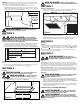
SECTION 7
Finishing the Installation
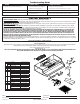
1. Install the appropriate filter sliding the back side of the filter into the tab and pressing the
front of the filter into place (Figure 9).
2. Turn switches to the “OFF” position and restore power. Test that the light and the fan are
operating properly.
3. If there is any vibration noise, check for the source and try to tighten fasteners.
SECTION 8
Operation
Controls
Your Range Hood is equipped with two rotary switches with one controlling the lighting and the
other controlling the exhaust fan. The light switch has three positions, HIGH ( ), LOW ( ), and
OFF ( ).The fan switch is an infinite speed control that can be adjusted to your desired setting.
Rotating the switch counter clockwise until you hear a click will turn the hood off.
SECTION 9
Maintenance
CAUTION: MAKE SURE POWER IS SWITCHED OFF AT
SERVICE PANEL BEFORE SERVICING THE UNIT.
Filters
Grease Filter - Included with your range hood is an aluminum grease filter that should be
washed in hot water with detergent once a month. Reverse the instructions in the “Finishing
the Installation” section of the instructions to remove filter. If the grease filter becomes
damaged, replace with Air King Model RF35 Grease Filter.
Charcoal Odor Filter - If you have installed an optional combination grease/charcoal filter,
it cannot be washed and must be discarded and replaced when it becomes noticeably dirty,
has stopped filtering the odors, or at least once per year. Replace with Air King Model RF55
Combination Odor/Grease Filter.
Cleaning
CAUTION: DO NOT USE GASOLINE, BENZINE, THINNER, HARSH
CLEANSERS, ETC., AS THEY MAY DAMAGE THE RANGE HOOD.
1. Clean your range hood with a mild detergent, such as dishwashing liquid, and dry with
a soft cloth. NEVER USE ANY ABRASIVE PADS OR SCOURING POWDERS. Completely dry
before restoring power. NEVER IMMERSE ELECTRICAL PARTS IN WATER.
2. The fan assembly can be vacuumed when build up (dirt, lint, etc.) accumulates over time.
The fan is permanently lubricated and does not require oiling.
CALIFORNIA RESIDENTS ONLY:
WARNING: THIS PRODUCT CAN EXPOSE YOU TO A CHEMICAL [OR
CHEMICALS] KNOWN TO THE STATE OF CALIFORNIA TO CAUSE CANCER.
WARNING: THIS PRODUCT CAN EXPOSE YOU TO A CHEMICAL [OR
CHEMICALS] KNOWN TO THE STATE OF CALIFORNIA TO CAUSE REPRODUCTIVE
TOXICITY.
Figure 9
NOTE: If installing into existing construction and you will not have access to the ductwork once the
hood is in place, make ducting connections at this point. Refer to the Ducting Section for instructions.
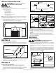
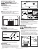
5. Install the 4 mounting screws at the previously marked locations. Leave approximately 1/8"
clearance. Slide the hood in place through the keyhole slots and align the front of the hood
so that it is flush with the front of the cabinets. Tighten all screws securely (Figure 6).
CAUTION: DO NOT INSTALL CLOSER THAN 22 INCHES ABOVE
COOKING SURFACE.
SECTION 5
Wiring
CAUTION: ALL ELECTRICAL CONNECTIONS MUST BE
MADE IN ACCORDANCE WITH LOCAL CODES, ORDINANCES, OR
NATIONAL ELECTRICAL CODE. IF YOU ARE UNFAMILIAR WITH METHODS OF INSTALLING
ELECTRICAL WIRING, SECURE THE SERVICES OF A QUALIFIED ELECTRICIAN.
1. Connect the 2 loose White wires from the range hood to the White wire from the supply,
and the loose Black wire from the range hood to the Black wire of the supply. Connect
the ground wire (green or bare) from the supply to the green ground screw of the hood.
Use approved methods for all connections (Figure 7).
NOTE: DO NOT disconnect any wiring that has already been crimped with a wire connector
from the factory.
2. Install the wire compartment cover and tighten screw. Make sure all wiring is securely
contained within the wire compartment.
SECTION 6
Ducting
CAUTION: ALL DUCTING MUST COMPLY WITH LOCAL AND NATIONAL
BUILDING CODES.
WARNING: TO REDUCE THE RISK OF FIRE, USE ONLY
METAL DUCTWORK.
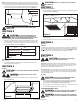
1. Connect the ducting to the hood’s duct collar and damper. Secure in place using tape to
seal all joints (Figure 8).
Figure 6
1/8"
Keyhole
Figure 8
Figure 7
Supply from house
Black
Neutral (White) from Light
Ground (Green or Bare)
Hood
Black
Neutral (White)
Green
Neutral (White) from Motor