
Installation Sheet

INSTALLATION INSTRUCTIONS
CAUTION:
MAKE SURE POWER IS SWITCHED OFF AT SERVICE
PANEL BEFORE STARTING INSTALLATION.
SECTION 1
Preparing the Exhaust Fan
1. Unpack fan from the carton and confirm that all pieces are present.
In addition to the exhaust fan you should have:
1 - Grill
1 - Damper Assembly (attached)
2 - Mounting Brackets
4 - #10-32 Nuts
1 - Instruction/Safety Sheet
2. Choose the location for your fan. To ensure the best air and sound
performance, it is recommended that the length of ducting and the
number of elbows be kept to a minimum, and that insulated hard
ducting be used. Larger duct sizes will
reduce noise and airflow restrictions.
This fan will require at least 10" of
clearance in the ceiling or wall, and will
mount through drywall up to 3/4" thick.
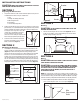
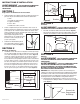
3. Select the most convenient electrical
knockout and remove using a straight-
blade screw driver (Figure 1).
SECTION 2
Mounting the Housing
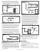
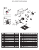
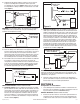
1. Installation on 24" Centers Joists or Larger than 2x6 Joists on 16"
Centers: Install two - 2x4 headers (not included) between the joists
(Figure 2). Install the mounting brackets through the top set of
slots on the fan housing and secure in place with the four included
#10-32 nuts as shown. Position the fan housing between the
headers and secure the mounting brackets with screws or nails
(not included) to the header. Adjust the height of the housing so
that it is flush with the finished ceiling by loosening the mounting
bracket nuts and sliding the housing up or down on the bracket.
Fully tighten all four nuts to secure the housing in place (Figure 3).
www.airkinglimited.com
A210572218 New 7-09 2 of 12
SECTION 3
Ducting
CAUTION: ALL DUCTING MUST COMPLY WITH LOCAL AND
NATIONAL BUILDING CODES.
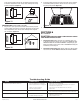
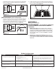
1. Connect the ducting to the fan’s duct collar (Figure 4). Secure
in place using tape or screw clamp. Always duct the fan to the
outside through a wall or roof cap.
SECTION 4
Wiring
CAUTION: MAKE SURE POWER IS SWITCHED OFF AT SERVICE
PANEL BEFORE STARTING INSTALLATION.
CAUTION: ALL ELECTRICAL CONNECTIONS MUST BE MADE
IN ACCORDANCE WITH LOCAL CODES, ORDINANCES, OR NATIONAL
ELECTRICAL CODE. IF YOU ARE UNFAMILIAR WITH METHODS OF
INSTALLING ELECTRICAL WIRING, SECURE THE SERVICES OF A
QUALIFIED ELECTRICIAN.
NOTE: This unit includes a side access panel for wiring that does not
require the removal of the fan’s blower assembly. If you choose to wire
the unit from the inside, you will need to remove the blower assembly
and internal wiring compartment. Both methods are equally effective.
1a. External Wire Compartment: Remove the wire compartment
cover screw and place cover in a secure place (Figure 5).
Figure 1
Bracket
Housing
Nut
Header
Figure 2
Figure 3
Joist
2 x 4 Header
2 x 4 Header
Joist
Ceiling
Ducting
Duct
Collar
Figure 4
Figure 5
Screw
Wire
Compartment
Cover