
Full Product Manual


INSTALLATION INSTRUCTIONS
CAUTION:
MAKE SURE POWER IS SWITCHED OFF AT
SERVICE PANEL BEFORE STARTING INSTALLATION.
SECTION 1
Preparing the Range Hood
1. Unpack hood from the carton and confirm that all pieces are present. In addition to the
range hood you should have:
2 - Aluminum Grease Filters (36" models - 3)
2 - GU10 Base, 6.5W LED Lamp
1 - 3-1/4" x 10" Damper
1 - 7" Round Damper
10 - Damper Mounting Screws
4 - #8 Mounting Screws
1 - Instruction/Safety Sheet
NOTE: Some hoods may be shipped with a protective plastic adhered to the range hood. It is
recommended to leave this in place during installation to protect the hood from scratching.
Remove when the installation is complete.
TIP: Use a hair dryer to warm the plastic coating. This will allow the coating to easily release
from the hood.
2. Lay the hood flat on a table so the underside is facing you. Use a piece of cardboard to
avoid damaging the table or the hood.
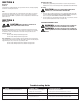
3. Remove the following items from the hood and place in a safe place until needed (Figure 1):
Grease filters: Pull on tabs to remove.
Damper and Lamp Box: Both the damper assemblies and lamps are contained with the
box located on the inside of the hood. Remove and place in a safe place until needed.
Wire compartment cover: Remove the screws holding it in place.
4. Install the included 6.5 watt GU10 LED lamps into the lamp holder by lining up the pins
on the lamp base to the socket of the lamp holder and turning the lamp body clockwise
until the lamp snaps into place and is firmly seated in the lamp holder.
SECTION 2
Prepare the location for Hood Support
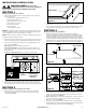
1. If the hood will be installed under cabinets that have a recessed bottom, it will be necessary
to install wood mounting strips (not included) so the hood will mount properly (Figure 2).
www.airkinglimited.com
6728036 Rev. i 5-17 2 of 12
2. The thickness of the strips should be the same as the recess of the cabinet and they
should be approximately 2" wide.
3. Install the strips using appropriate length wood screws (not included). Make sure the
strips line up to the keyhole slots of the range hood.
SECTION 3
Prepare the Hood for Installation
1. Choose the type of ducting you will require. To ensure the best air and sound performance,
it is recommended that the length of ducting and the number of elbows be kept to a
minimum, the radius of each elbow be as large as possible for the installation, and that
hard ducting be used. Larger duct sizes will reduce noise and airflow restrictions. This
model is equipped to vent either Vertically or Horizontally through a 3-1/4" x 10" duct or
through a 7" round duct. It can be modified to be ductless (re-circulates the air back into
the kitchen) with the addition of a model CF-09S Charcoal Filter (not included) (Figure 3).
2a. Horizontal or Vertical - Remove the rectangular knockout by inserting a screw driver under
the edge and break the tabs holding it in place. Peel back with pliers (Figure 4).
2b. Ductless - From inside the hood, depress the latches with your fingers before removing
the shutter. Pull down on the tab in front of the fan blade. Bend the shutter at the creased
area and break the top part of the shutter off and discard. Insert the remaining part of the
shutter back into the slot (Figure 4).
2c. 7" Round - Remove the round knockout located on the top of the hood by inserting a screw
driver under the edge and break the tabs holding it in place. Peel back with pliers (Figure 4).
3. Determine where the electrical service will enter the hood and remove the appropriate
electrical knockout by inserting a screw driver into the slot and rocking back and forth until the
knockout comes loose (Figure 4).
SECTION 4
Installing the Range Hood
CAUTION: MAKE SURE POWER IS SWITCHED OFF AT
SERVICE PANEL BEFORE STARTING INSTALLATION.
1. Once the proper knockout(s) have been removed, either hold the hood up to the installation
location and mark the locations of the ducting (if applicable), electrical, and mounting holes
or mark the locations by measurement.
2. Cut appropriate holes for ducting connection (if applicable) and electrical connection in the
wall/cabinet.
Figure 2
Wood Strip
Figure 3
Horizontal
Vertical
Ductless
Figure 4
Horizontal Vertical Ductless
Figure 1
Motor
Wire
Compartment
Cover
Grease
Filter