
Installation Guide


NOTE: This fan is rated for direct insulation contact (Type IC) and it is recommended that this fan
be completely covered by insulation in order to reduce heat loss or gain to unconditioned space.
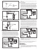
2. If the fan’s blower assembly was removed during the wiring process, reinstall the
blower by reversing the directions in Section 5 (Wiring), Step 1b.
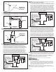
3a. STANDARD AND MOTION SENSING
MODELS: Plug the fan’s 2 pin and 3
pin quick connect motor cords into the
corresponding receptacle located on the
wire compartment cover. These cords
will only fit one way into the receptacles
(Figure 11).
3b. HUMIDITY SENSING MODELS: Plug the
fans 2 pin and 3 pin quick connect motor
cords into the corresponding receptacle
located on the wire compartment cover.
Connect the two pin connector from
the humidistat compartment to the two
pin connector from the side of the wire
compartment cover. These cords only fit
one way into the receptacles.
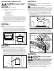
4. Install the ceiling mounting flange to cover any gaps which exist between the housing
and the finished ceiling. Remove the two screws that connect the ceiling mounting flange
to the housing. Put sealant (not provided) on inside edge of the ceiling mounting flange
to ensure that the flange is sealed to the ceiling. Line up the screw holes in the ceiling
mounting flange with the screw holes on the inside of the housing and press flange in
place so it is tight against the ceiling. Reinstall ceiling flange mounting screws inside the
housing (Figure 12).
NOTE: If the housing is mounted to far or not far enough into the ceiling for the flange to make
a solid connection, loosen the mounting channel and adjust the housing up or down on the
rails. Once in place, fully tighten the mounting channel nuts.
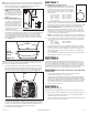
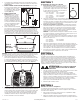
5. Install the grill by squeezing the springs together and installing it up into the slot furthest
from the wire compartment on the fans housing. Attach the 4 pin quick connect from the
grill to the 4 pin connector on the top of the wire cover. The cord will only fit one way into
the receptacle. Install the other spring and push the grill up into position. (Figure 13).
6. Open the light lens on the grill by pushing into the lens and allowing in to spring open.
Install the 8 watt lamp (included) into the lamp holder by lining up the pins on the lamp
base to the socket of the lamp holder and turning the lamp body clockwise until the lamp
snaps into place and is firmly seated in the lamp holder. Install a 4 watt maximum type
C7 (candelabra base) night light (not included) into the side lamp holder.
7. Restore power and test your installation.
www.airkinglimited.com
6727913 Rev. F 6-17 4 of 12
SECTION 7
Programming the Occupancy Sensor
1a. Setting the Occupancy Time Delay. This will set the amount
of time the fan will continue to operate on high speed after the
room is vacated. Locate the motion sensor on the fan’s grill
and press the button 2 times. The LED on the sensor will then
flash the number of times to indicate the current setting, this
will repeat 3 times:
1 time = 30 seconds 6 times = 12.5 minutes
2 times = 2.5 minutes 7 times = 15 minutes
3 times = 5 minutes 8 times = 17.5 minutes
4 times = 7.5 minutes 9 times = 20 minutes
5 times = 10 minutes
1b. To adjust the setting, while the sensor is still flashing from Step 1a, press the button the
number of times that corresponds with the amount of time you desire, for instance 3 times
sets the delay to 5 minutes (see numbers in Step 1). The sensor will then flash the number
of times for the new setting 3 times before exiting back to the programming mode.
2a Setting the Minimum On Time. This sets the minimum time the fan will operate on
high speed once motion is detected within the room. This works in conjunction with
the Occupancy Time Delay feature set in Steps 1a and 1b. For instance if you set the
minimum time on for 15 minutes and the Time Delay for 5 minutes, the fan will operate
for at least 15 minutes then 5 additional minutes.
NOTE: This is a minimum time that the fan will operate. If the room is occupied longer, the
fan will continue to run until the room is vacated and the occupancy time delay has elapsed.
2b. Locate the motion sensor on the fan’s grill and press the button 10 times. The LED on
the sensor will then flash the number of times to indicate the current setting, this will
repeat 3 times:
1 time = 0 minutes 4 times = 45 minutes
2 times = 15 minutes 5 times = 60 minutes
3 times = 30 minutes
2c. To adjust the setting, while the sensor is still flashing from Step 2b, press the button
the number of times that corresponds with the amount of time you desire, for instance
3 times sets the minimum on time to 30 minutes (see numbers in Step 2b). The sensor
will then flash the number of times for the new setting 3 times before exiting back to
the programming mode.
3. Once all setting have been made and the sensor will return to detection mode and the
LED will flash when occupancy of the room is detected.
SECTION 8
Setting the Humidistat
This fan may be equipped with a humidity sensor that automatically turns the fan on (or to
high speed on dual speed models) when humidity is above set point and off (or back to low
speed on dual speed models) when humidity is at or below set point. If the fan is operating
too long or not enough, first check to see the humidity sensor set point. In cases where the
ambient humidity level of the room rises higher than the preset level, the fan will turn on even
if the room is not occupied. This helps prevent conditions that lead to mold growth.
CAUTION: MAKE SURE POWER IS SWITCHED OFF AT SERVICE PANEL BEFORE
SERVICING THE UNIT.
1. To set the desired humidity level of the room, remove the grill and locate the
dehumidistat dial located on the wire compartment cover.
2. Set the dial to the relative humidity you want the fan to maintain usually between 50 &
80%. Moist climates will require higher settings than dry climates. When the humidity
level of the room is below this setting the fan will remain off (or low speed on dual speed
models). When the humidity level rises above this setting the fan will turn on (or to high
speed on dual speed models) and run until the humidity level falls below this setting.
3. Reinstall the grill and restore power.
SECTION 9
Activating the Boost Speed
Should it be determined that additional flow is necessary due to excessive duct resistance or
other field conditions this model is equipped with a boost speed. To activate the boost speed:
1. Remove the grill and find the rocker switch located on the triangular shaped wiring
compartment in the corner of the fan housing.
2. Push the rocker switch to the Boost position and reinstall grill. The fan will operate at the
boost speed any time it changes to high speed.
Figure 12
Screws
Ceiling
Mounting
Flange
Screw Holes
Figure 11
Figure 13