
Installation Guide


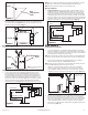
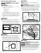

1b. Internal Wire Compartment: If the motor is already installed in the housing, remove the
two screws holding the blower assembly in place. Lift up on the assembly and slide it
out of the tabs on the housing (Figure 6). Remove the wire compartment cover screw
and place the cover in a secure place (Figure 7).
NOTE: If the fan motor plug is connected to the fan housing receptacle, unplug so the blower
assembly can be completely removed.
Single Speed Models
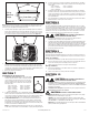
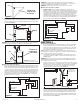
2. Secure the electrical wires to the housing with an approved electrical connector.
Connect the White wire of the fan to the White (Neutral) wire from the power source.
Connect the ground wire from the house to the green wire from the fan housing. Using
a properly grounded three function switch (not included) connect the Black wire from
the supply to the switch. Connect the Black wire (fan) from the fan housing to one of the
terminals on the switch. Connect the Red wire (light) from the fan housing to a separate
terminal on the switch. Connect the Purple wire (night light) from the fan housing to a
separate terminal on the switch (Figure 8). Use approved methods for all connections.
www.airkinglimited.com
6727914 Rev.D 4-17 3 of 12
NOTE: The fan’s receptacle wires might need to be pulled outside compartment for connection.
Only pull the five loose wires outside of compartment. Additional wires will be present.
NOTE: Unit must be grounded according to all local and national codes.
Dual Speed Models
3. Continuous Ventilation: For two speed fans wired for continuous ventilation, connect
the White wire of the fan to the White (Neutral) wire from the power source. Connect the
ground wire from the house to the green wire from the fan housing. Connect the Black
wire of the fan to the Black wire (Hot) from the power source. Using a properly grounded
standard duplex toggle switch (such as Leviton 5224-2W, not included) connect the Black
wire from the supply to one side of the top and bottom switch. Connect the Red wire (light)
from the fan housing to the other side of the top switch and connect the Purple wire (night
light) from the fan housing to the other side of the bottom switch (Figure 9).
SECTION 6
Completing the Installation
1. Use a sealant appropriate for contact with the building materials present and for the
temperature requirements of the installation to prevent air leakage from unconditioned
spaces is recommended. If gaps between unit housing and ceiling are great, additional
material (backing rod, ceiling material) may be required.
NOTE: This fan is rated for direct insulation contact (Type IC) and it is recommended that this fan
be completely covered by insulation in order to reduce heat loss or gain to unconditioned space.
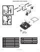
2. If the fan’s blower assembly was removed during the wiring process, reinstall the
blower by reversing the directions in Section 5 (Wiring), Step 1b.
NOTE: An extra 2-pin connector with tape over it may be present. This is utilized for the boost
speed. See Section 9 (Activating the Boost Speed) for more details.
3. Plug the fan’s 2 pin and 3 pin quick connect motor cords into the corresponding
receptacle located on the wire compartment cover. Connect the two pin connector
from the humidistat compartment to the two pin connector from the side of the wire
compartment cover. These cords will only fit one way into the receptacles (Figure 10).
4. Install the ceiling mounting flange to cover any gaps which exist between the housing
and the finished ceiling. Remove the two screws that connect the ceiling mounting
flange to the housing. Put sealant (not provided) on inside edge of the ceiling mounting
flange to ensure that the flange is sealed to the ceiling. Line up the screw holes in the
ceiling mounting flange with the screw holes on the inside of the housing and press
flange in place so it is tight against the ceiling. Reinstall ceiling flange mounting screws
inside the housing (Figure 11).
Figure 5
Screw
Wire
Compartment
Cover
Figure 9
Supply from house
Black
Neutral (White)
Ground (Green or Bare)
Wire Compartment
Black
Neutral (White)
Green
Switch
Black
Purple
Red
Figure 8
Supply from house
Black
Neutral (White)
Ground (Green or Bare)
Wire Compartment
Neutral (White)
Green
Switch
Black
Purple
Red
Screw
Wire Compartment
Cover
Figure 7
NOTE: Wire compartment configuration
will be dependent on model.
Plug
Tabs
Screws
Figure 6
Figure 10
NOTE: Wire compartment
configuration will be
dependent on model.