
Instructions / Assembly
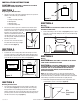
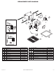
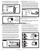

1b. Internal Wire Compartment: Using a 7/16" socket, remove the two hex nuts
holding the blower assembly in place. Lift up on the assembly and slide it
out of the tabs on the housing (Figure 6). Remove the wire compartment
cover screw and place the cover in a secure place (Figure 7).
NOTE: If the fan motor plug is connected to the fan housing receptacle,
unplug so the blower assembly can be completely removed.
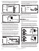
SINGLE SPEED UNITS (models ES80SH and ES130SH)
2a. For proper operation the humidity sensing fan will require a 3 way
switch (not included). Run wiring between the fan and the switch
location. Make sure you leave enough wiring in each box to make the
connections. At the switch box connect the black wire from the house
to the common terminal of the switch. Connect the black wire from
the fan to one of the switched terminals on the switch. This position
will energize the automatic mode and the fan will energize upon a rise
in humidity. Connect the red wire from the fan to the other switched
terminal on the switch. This position will activate the Manual On
feature and energize the fan. Properly connect the ground and neutral
(if applicable) mount the switch and the cover.
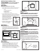
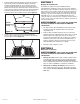
2b. From where you have chosen to access the fan’s junction box, connect
the white wire from the house to the white wire from the fan. Connect
the wire from the automatic position on the wall switch to the black
wire from the fan, connect the wire from the manual On position on
the switch to the red wire from the fan. Connect the ground wire from
the house to the green wire from the fan housing (Figure 8). Use
approved methods for all connections.
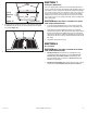
TWO SPEED UNITS (models ES80DH and ES130DH)
3. Continuous Ventilation: For two speed fans wired for continuous
ventilation, connect the White wire of the fan to the White (Neutral)
wire from the power source. Connect the ground wire from the house
www.airkinglimited.com
6728020 New 3-12 3 of 12
to the green wire from the fan housing. Connect the Black wire of the
fan to the Black wire (Hot) from the power source. The fan will operate
on low speed continuously and boost to high upon a rise in humidity.
A manual override switch (not included) can be used to provide a
manual fan Off function. (Figure 9).
NOTE: The fan’s receptacle wires might need to be pulled outside
compartment for connection. Only pull the five loose wires outside of
compartment. Additional wires will be present.
NOTE: Unit must be grounded according to all local and national codes.
4. Carefully tuck wire back inside wire compartment and replace wire
compartment cover securing with the screw that was removed earlier.
SECTION 6
Completing the Installation
1. If the fan’s blower assembly was removed during the wiring process,
reinstall the blower by reversing the directions in Section 4 (Wiring),
Step 1b.
2. Plug the fan’s 3 pin quick connect motor cord into the receptacle
located on the side of the wire compartment cover. Plug the 2 pin
quick connect motor cord into the receptacle from the capacitor on
single speed models (ES80SH, ES130SH), or on the side of the wire
compartment on dual speed models (ES80DH, ES130DH). These cords
will only fit one way into the receptacles (Figure 10).
3. Install the ceiling mounting flange to cover any gaps which exist
between the housing and the finished ceiling. Line up the slots in the
ceiling mounting flange with the screws on the inside of the housing
and press flange in place so it is tight against the ceiling. Tighten
both screws inside the housing. Install drywall screws (not included)
through the holes in the flange and into the ceiling. Install as many
drywall screws needed to ensure the flange fits tightly against the
ceiling (Figure 11).
Plug
Tabs
Hex Nuts
Figure 6
Figure 7
Screw
Wire Compartment
Cover
Humidity Set
Point Knob
NOTE: Wire compartment configuration will be dependent on model.
Figure 9
Supply from house
Ground
White
Hot (Black)
Figure 8
Supply from house
Ground
White
Hot (Black)
Red
Figure 10
SINGLE SPEED UNITS
DUAL SPEED UNITS