
Instructions / Assembly
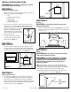
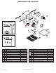
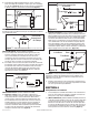

1b. Internal Wire Compartment: Using a 7/16" socket, remove the two hex
nuts holding the blower assembly in place. Lift up on the assembly
and slide it out of the tabs on the housing (Figure 6). Remove the
wire compartment cover screw and place the cover in a secure place
(Figure 7).
NOTE: If the fan motor plug is connected to the fan housing receptacle,
unplug so the blower assembly can be completely removed.
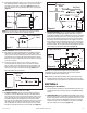
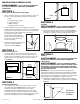
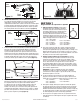
SINGLE SPEED UNITS (models ES80SG and ES130SG)
2a. Run wiring from an approved wall switch (not included) carrying the
appropriate rating. One neutral (white), one ground (green or bare
copper), and one hot (black lead connected to the switch). Secure the
electrical wires to the housing with an approved electrical connector.
Make sure you leave enough wiring in the box to make the connection
to the fan’s receptacle.
2b. From where you have chosen to access the fan’s junction box,
connect the white wire from the house to the white wire from the
fan’s receptacle. Connect the black wire from the wall switch to the
black wire from the fan’s receptacle. Connect the ground wire from
the house to the green wire from the fan housing (Figure 8). Use
approved methods for all connections.
TWO SPEED UNITS (models ES80DG and ES130DG)
3a. Continuous Ventilation: For two speed fans wired for continuous
ventilation, connect the White wire of the fan to the White (Neutral)
wire from the power source. Connect the ground wire from the house
to the green wire from the fan housing. Run 2 wires from a properly
grounded wall switch (not included) to the fan. Connect the Black
wire of the fan to the Black wire (Hot) from the power source. Connect
the Hot Yellow wire from the fan to the input of the switch. Connect
the second Yellow wire from the fan to the output side of the switch.
Closing the switch will change from normal to high speed (Figure 9).
www.airkinglimited.com
A210572215 Rev. B 5-12 3 of 12
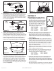
3b. Intermittent Ventilation: For two speed fans wired for intermittent
ventilation with a standard duplex toggle switch (such as Leviton
5224-2W not included). Connect the White wire of the fan to the White
(Neutral) wire from the power source. Connect the ground wire from
the fan to the ground wire from the power source. Properly ground
the switches. Connect the black wire from the supply to one side of
the top switch. Connect the black wire from the fan to the other side
of the top switch, Connect 1 yellow wire from the fan to each side of
the bottom switch. The top switch turns the fan On & Off, the bottom
switch changes speed between high and low (Figure 10).
NOTE: The fan’s receptacle wires might need to be pulled outside
compartment for connection. Only pull the five loose wires outside of
compartment. Additional wires will be present.
NOTE: Unit must be grounded according to all local and national codes.
4. Carefully tuck wire back inside wire compartment and replace wire
compartment cover securing with the screw that was removed earlier.
SECTION 6
Completing the Installation
1. If the fan’s blower assembly was removed during the wiring process,
reinstall the blower by reversing the directions in Section 4 (Wiring),
Step 1b.
2a. SINGE SPEED UNITS (models ES80SG and ES130SG): Plug the fan’s 2
pin quick connect motor cord into the receptacle located on the side of
the wire compartment cover. Plug the 3 pin quick connect motor cord
into the shorter end of the included harness then into the receptacle
located on the top of the wire compartment cover These cords will
only fit one way into the receptacles (Figure 11).
Figure 8
Supply from
house
Ground
White
Hot (Black)
Figure 7
Screw
Wire Compartment
Cover
Figure 9
Supply from
house
Hot (Black)
Black
Yellow
Yellow
Switch
Neutral
(White)
Ground (Green or Bare)
Figure 10
Supply from house
Hot
(Black)
Yellow
Black
Switch
Fan
Ground (Green or Bare)
Neutral (White)
Yellow
Plug
Tabs
Hex Nuts
Figure 6
NOTE: Wire compartment configuration will be dependent on model.