
Installation Guide


INSTALLATION INSTRUCTIONS MODELS FRAS90/120
FRAK50S/80/90/100/110/130
READ AND SAVE THESE INSTRUCTIONS.
IMPORTANT SAFEGUARDS.
CAUTION: To reduce the risk of fire and to properly exhaust air, be sure to duct air outside. Do Not vent exhaust air into spaces
within walls or ceilings or into attics, crawl spaces, or garages.
WARNING: To reduce the risk of fire or electric shock, Do Not use this fan with any solid-state speed control device.
WARNING: TO REDUCE THE RISK OF FIRE OR ELECTRIC SHOCK OR INJURY TO PERSONS OBSERVE THE FOLLOWING.
a) Use this unit only in the manner intended by the manufacturer. If you have any questions, contact the manufacturer.
b) Before servicing or cleaning unit, switch power off at service panel and lock the service disconnecting means to prevent
power from being switched on accidentally. When the service disconnecting means cannot be locked, securely fasten a
prominent warning device, such as a tag, to the service panel.
CAUTION: For general ventilating use ONLY. DO NOT use to exhaust hazardous or explosive materials and vapors.
WARNING: TO REDUCE THE RISK OF FIRE, ELECTRIC SHOCK OR INJURY TO PERSONS, OBSERVE THE FOLLOWING.
a) Installation work and electrical wiring must be done by a qualified person (s) in accordance with all applicable codes and
standards, including fire-related construction.
b) Sufficient air is needed for proper combustion and exhausting of gases through the flue (chimney) of fuel burning equipment
to prevent back drafting. Follow the heating equipment manufacturer's guideline and safety standards such as those published
by the National Fire Protection Association (NFPA) and the American Society of Heating, Refrigeration, and Air-Conditioning
Engineers (ASHRAE), and the local code authorities.
c) When cutting or drilling into wall or ceiling, do not damage electrical wiring and other hidden utilities.
d) Ducted fans must always be vented to the outdoors.
e) If this unit is to be installed over a tub or shower, it must be marked as appropriate for the application and be connected to a
GFCI (Ground Fault Circuit Interrupter) - protected branch circuit.
f) NEVER place a switch where it can be reached from a tub or shower.
IF YOU DISCOVER ANY MISSING COMPONENTS OR DAMAGE CALL 1-800-465-7300 BETWEEN 8:00 AM &
3:30 PM EASTERN TIME MONDAY TO FRIDAY.
________________________________________________________________________
________________________________________________________________________
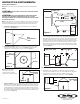
FIGURE 2.
210572084
9-3/8"
10-7/16"
8-1/8"
11-5/16"
9-1/2"
1"
12-15/16"
10-5/16"
11/16"
SUB FLOOR
RECTANGULAR SECTION OF 3/8" FIRE RATED GYP
BOARD MINIMUM 18" LONG BY WIDTH OF JOIST
SPACE (SEE #1: INSTALLATION LOCATION).
REQUIREMENTS FOR INSTALLATION IN UL/ULC RATED CEILING ASSEMBLIES
SEE UL AND ULC FIRE RESISTANCE DIRECTORY
FINISHED
CEILING
GRILL
MOUNTING
SCREW
METAL
GRILL
CEILING
RADIATION
DAMPER
DAMPER
MOUNTING
SCREW
DAMPER
MOUNTING
FRAME
FAN HOUSING
5/8" F.R. GYP BOARD TO COVER TOP OF FAN
FAN HOUSING
MOUNTING RAIL
FAN HOUSING
MOUNTING SCREW
AND WASHER
MIN. LENGTH 1.5"
This fan must be installed as per UL and CUL rated ceiling assembly
(refer to fig. 2). This will require the installation of a minimum 3/8" fire
rated gypsum board under the subfloor and a minimum 5/8" gypsum
board to cover the top of the fan housing.
To install this fan you should not have to remove the fan's blower
assembly. You gain access to the wiring compartment via the
triangular wire cover on the outside of the fan housing. If for some
reason you wish to remove the fan's blower it is secured in place with
one screw through the venturi, once removed you can release the
blower from the lances in the housing and lift the blower out. Place it
somewhere so it does not get damaged.
MOUNTING THE HOUSING. REFER TO FIG. 2.
AS SHOWN BELOW THE CEILING DAMPER FRAME WILL REQUIRE A
CUTOUT OF 11-5/16" x 9-1/2". AFTER THE INSTALLATION IS COMPLETE,
SEAL ANY GAPS BETWEEN THE DAMPER FRAME AND CEILING
DRYWALL WITH CAULK CARRYING THE APPROPRIATE UL RATING.
1. Select the best location to mount the housing in the ceiling. As per
UL and CUL fire resistance construction, install a minimum 3/8" Fire
Rated gypsum board 18" long so that it is centered above the fan. The
gypsum board must span the distance between the joists, typically
14.5" for joists on 16" centers.
2. Select the most convenient electrical knockout and remove it,
remove the triangular wire cover.
3. Insert the 4 slide rails into the channels on the housing side.
4. Adjust the housing height so the housing will be flush with the
finished ceiling.
5. Secure the 4 slide rails to the joist using wood screws. Make sure
you install a washer at the head of each screw as shown below. This
will ensure the screw head does not slip out of the mounting rail.
6. Once the 4 slide rails have been secured in place you will have to
install the 2 rail supports on both sides of the housing. They hook
onto the bottom of the rail channels and are secured at the top via two
screws.
DUCTING.
Note: All ducting must comply with local and national building codes.
1. Ensure any tape holding the damper in place is removed and that
the damper is operating freely.
2. Connect the ducting to the fan's duct collar. Secure in place using
duct tape or a screw clamp. Always duct the fan to the outside
through a wall or roof cap.
ELECTRICAL WIRING.
CAUTION: MAKE SURE THE POWER IS TURNED OFF BEFORE
BEGINNING THIS INSTALLATION.
FIG. 1.
Note: All wiring must comply with local and national codes. You
MUST ground this fan.
1. Run wiring from an approved wall switch carrying the appropriate
rating. One neutral (White), one ground (Green or Bare Copper), and
one hot (Black lead connected to the switch). Secure the electrical
wires to the housing using an approved electrical connector. Make sure
you leave enough wiring in the box to make connection to fan's wiring.
2. Connect the white wire to the white wire on the fan's receptacle.
Connect the black wire to the black wire on the fan's receptacle.
Connect the ground from the house to the fan's ground.
3. Retrieve the fan's triangular wire cover and secure in place with the
#6 screw removed earlier.
4. From below spin the fan's blower wheel to ensure it moves freely.
COMPLETING THE INSTALLATION.
Once the fan housing has been installed and the ceiling drywall is in
place you can complete the fan’s installation
CEILING DAMPER & GRILL INSTALLATION.
CAUTION: The ceiling damper supplied is spring loaded and has the
potential to release suddenly when handled improperly. A damaged
spring or defective fusible link can allow the damper to close violently
into the handler's hand or arm, causing serious injury. Care should be
exercised when handling and installing spring loaded dampers. It is
recommended that gloves be worn by handlers and installers.
The ceiling damper supplied with the unit is designed to install only in
Air-King Model AKFH2 housings.
1. Install the ceiling damper & ceiling damper frame into the opening
of the fan housing. The ceiling damper frame is designed to fit on the
outside of the housing and the ceiling damper will sit on the inside of
the fan housing.
2. Once positioned in place secure the ceiling damper frame to the fan
housing using two of the supplied #8 x 1" screws. Carefully drive the
screws through the two oblong slots on the ceiling damper frame into
the screw retaining lances on each side of the fan housing. Complete
this step slowly as you do not want to damage the lances on the housing.
3. Once the ceiling damper is installed and secure, position the metal
fan grill in place aligning the two holes in the fan grill with the two
extruded holes on the ceiling damper frame. Use the remaining two
#8 x 1" screws to secure the grill onto the fan.
CARE AND MAINTENANCE
CAUTION - BEFORE CLEANING OR SERVICING TURN OFF THE POWER
TO THE FAN.
1. Clean the grill using a mild soap or detergent only, no abrasives.
2. The fan motor is permanently lubricated, DO NOT oil the motor.
3. Once a year it is a good idea to inspect and clean the internal parts of
the fan, over time debris will build up on the fan blade causing the motor
to work harder than it should. When cleaning the internal parts be
extremely careful working around the spring loaded ceiling damper. Wear
gloves and use a vacuum with an extension hose to clean inside the fan.
SEE DETAILS ON UL CLASSIFICATION
MARKING ON ENCLOSED PRODUCT