
Owner's Manual


INSTALLATION INSTRUCTIONS
CAUTION:
MAKE SURE POWER IS SWITCHED OFF AT SERVICE PANEL
BEFORE STARTING INSTALLATION.
SECTION 1
Preparing the Range Hood
1. Unpack hood from the carton and confirm that all pieces are present. In addition to
the range hood you should have:
2 - Chimney Sections
1 - Package containing:
1 - duct collar
2 - chimney brackets
8 - #6 x 1" mounting screws with wall anchors
2 - #6 x 3/8" self threading screws (chimney upper)
30" models: 2 - Aluminum Grease Filters (shipped installed)
36" models: 3 - Aluminum Grease Filters (shipped installed)
2 - 50 Watt Halogen Lamps
1 - Instruction/Safety Sheet
NOTE: Some hoods may be shipped with a protective plastic adhered to the range
hood. It is recommended to leave this in place during installation to protect the hood
from scratching. Remove when the installation is complete.
SECTION 2
Installing the Range Hood
CAUTION: MAKE SURE POWER IS SWITCHED OFF AT SERVICE PANEL
BEFORE STARTING INSTALLATION.
CAUTION:WHEN CUTTING OR DRILLING INTO WALL DO NOT DAMAGE
ELECTRICAL WIRING AND OTHER HIDDEN UTILITIES.
1. Locate and mark the upper keyhole positions on the wall. If installing onto drywall,
drill holes into wall using a 3/16" drill bit. Install wall anchors into the drilled holes
(one for each hole). Install (2) provided #6 x 1" screws, leaving a 1/8" gap between the
screw head and the wall. If installing into other material (brick, cement, plaster, etc.)
choose an appropriate fastner capable of supporting the weight of the hood. Line up
the keyholes in the hood with the screws and position in place. Hang the hood over
the keyhole anchors and verify that the hood is centered, plum and level (Figure 1).
2. With the hood hanging in place from the top screws, mark the location of the lower
holes. If installing onto drywall, remove the hood and drill holes into wall using a 3/16"
drill bit. Install wall anchors into the drilled holes (one for each hole). If installing into
other material (brick, cement, plaster, etc.) choose an appropriate fastner capable
of supporting the weight of the hood. Hang the hood over the keyhole anchors and
verify that the hood is centered, level and the bottom holes line up with the anchors.
Install the provided #6 x 1" screws into the anchors (Figure 2). Tighten all screws
completely and reinstall the Grease filters.
www.airkinglimited.com
6728025 Rev. E 7-10 2 of 12
SECTION 3
Ducting
CAUTION: ALL DUCTING MUST COMPLY WITH LOCAL AND NATIONAL
BUILDING CODES.
WARNING: TO REDUCE THE RISK OF FIRE, USE ONLY METAL DUCTWORK.
1. Install the included duct collar to the hood with two of the provided #6 blunt tip
screws (Figure 3).
1. Connect the ducting to the duct collar and secure in place using tape to seal all
joints (Figure 3).
NOTE: To achieve proper air flow, 6" round ducting is required. The duct connector is 5.8" in
diameter (for 6" round ducting) and the center is located 3.1875" inches from the back wall.
CAUTION: ALWAYS DUCT THE FAN TO THE OUTSIDE THROUGH A WALL OR
ROOF CAP.
SECTION 4
Wiring
CAUTION: ALL ELECTRICAL CONNECTIONS MUST BE MADE IN ACCORDANCE
WITH LOCAL CODES, ORDINANCES, OR NATIONAL ELECTRICAL CODE. IF YOU ARE
UNFAMILIAR WITH METHODS OF INSTALLING ELECTRICAL WIRING, SECURE THE
SERVICES OF A QUALIFIED ELECTRICIAN.
1. Remove wire compartment cover by removing the screw then sliding it outward.
Choose the most convenient electrical knockout and remove using a straight-
blade screw driver.
2. Run wiring from an approved source carrying the appropriate rating. One neutral
(White), one ground (green or bare copper), and one hot (Black). Secure the electrical
wires to the wire compartment with an approved electrical connector. Make sure you
leave enough wiring in the box to make the connection to the hood.
3. Connect the White wire from the range hood to the White wire from the supply,
and the Black wire from the range hood to the Black wire of the supply. Connect
the ground wire from the home (green or bare) and the Green wire from the range
hood. Use approved methods for all connections. Reinstall the wire compartment by
sliding the tabs back into the holes then reinstalling the screw that was removed
eariler. Make sure all wiring is securely contained within the wire compartment
(Figure 4).
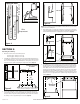
Figure 3
Duct Collar
Ducting
Hood
Figure 1
Upper Keyholes
Side View
Figure 2
Holes
Side View