
User's Manual


12
Technical Support
1-800-248-0892
Ext. 2
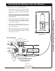
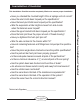
Installing the Air Lines
Air Line to
Bellows
Star
Washer
Vehicle body
or bumper
Hex Nut
Hex Nut
Rubber
Washer
Flat
Washer
Valve
Cap
Installing the RoadTamer System
Figure 15
Figure 16
Figure 17
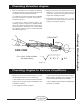
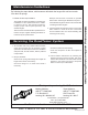
Frame Rail
Air
Lines
Tie Straps
Exhaust Pipes
Muffler
Keep air lines
secured at least 6"
away from all
heat sources
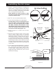
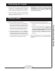
Good Cut
Air Line Cutting
Poor Cut
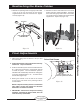
1. Choose a convenient location for mounting the
infl ation valves. Popular locations for the infl ation
valve are: the wheel well fl anges, the license plate
recess in the bumper, under the gas cap access
door, or through the license plate itself.
NOTE: Whatever the chosen location is, make
sure there is enough clearance for an air chuck
around the infl ation valves.
2. Drill a
5
/16 “ hole to install the infl ation valves.
3. Cut the air line assembly in two equal lengths.
CAUTION: When cutting or trimming the air line,
use a razor blade or a very sharp knife. A clean,
square cut will ensure against leaks. DO NOT
USE WIRE CUTTERS OR SCISSORS TO CUT
THE AIR LINE. These tools may fl atten or crimp
the air line, causing it to leak around the O-ring
seal inside the elbow fi tting (Figure 15).
4. Refer to Figure 16 to assist with air valve
installation.
5. Route the air line along the frame to the air fi tting
on the air spring. Keep at least 6” of clearance
between the air line and heat sources, such as the
exhaust pipes, muffl er, or catalytic converter (Figure
17). Avoid sharp bends and edges. Use the plastic
tie straps to secure the air line to fi xed, non-moving
points along the chassis. Be sure that the tie straps
are tight, but do not pinch the air line. Leave at least
2” of slack to allow for any movement that might pull
on the air line.
6. Cut off air line leaving approximately 12” of extra air
line. A clean square cut will ensure against leaks.
Insert the air line into the air fi tting. This is a push-
to-connect fi tting. Simply push the air line into the
straight fi tting until it bottoms out (
9
/16” of air line
should be in the fi tting).