
User's Manual


14
Technical Support
1-800-248-0892
Ext. 2
Checking Driveline Angles
Checking Driveline Angles
1. After the RoadTamer kit is installed, the following
conditions must be true for the driveline angles, both
at unloaded and fully loaded ride heights:
a. Condition #1: The operating angle at any individual
joint must be between 0.1° and 4°. The preferred
maximum angle is 2°.
b. Condition #2: When added together, the
operating angles throughout the driveline MUST
cancel. The operating angles at either end of a shaft
should be within 1° of each other or at least satisfy
the following formula in order to provide adequate
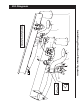
cancellation (Figure 21).
Figure 21
Checking Angles in Various Conditions
2. Wedge shims may be placed between the beams
and axle to correct driveline angles that fall
outside this requirement. Re-check all driveline
angles after installing the shims.
3. A minimum operating angle of 0.1° at each
universal joint is required to prevent dents from
forming on the bearing surfaces.
1. Measure and record the driveline angles in each of
the following conditions for later comparison:
a. The chassis as fi rst received (note that the driveline
angles may not conform exactly to this bulletin in this
incomplete condition).
b. The completed vehicle, unloaded.
SIDE VIEW
angle-a
angle-b
DRIVESHAFT
angle-c
For a 3-joint, 2-shaft driveline:
(as shown above)
a - b + c 4.0˚
22 2
c. The completed vehicle loaded to Gross Vehicle
Weight Rating (GVWR) with maximum front
Gross Axle Weight Requirement (GAWR).
d. The completed vehicle loaded to GVWR with
maximum rear GAWR.