
User's Manual

5
Technical Support
1-800-248-0892
Ext. 2
Installing the RoadTamer System
Attaching the Axle Beams
NOTE: For 4WD crew cab models, refer to the
manual provided with the driveshaft spacer kit
# 26029 (purchased seperately) at this time. You
must have this spacer kit before proceeding. If you
do not already have spacer kit # 26029, you can
purchase it by calling Air Lift’s Customer Service
Department at 800-248-0892, extension 1.
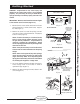
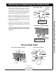
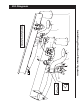
1. Attach the centering pins through each beam with
the round head facing down. Tighten the centering
pin nut securely (Figure 5).
2. Attach the driver-side beam assembly to the front
spring eye hanger using the supplied 16 mm bolt
(stock bolt on passenger side) and washer and the
previously removed stock nut (Figure 5). Be sure
to index the centering pin into the spring perch in
order to properly locate the axle and the beam.
Leave loose.
NOTE: The emergency brake cable should go
over the beam assembly.
3. Attach the beam assemblies to the axle with the
hardware shown in Figure 5. Secure snugly, but
do not completely tighten at this time.
NOTE: It will be necessary to use the stock
spring retainer between the u-bolts and the
beams.
NOTE: Draw the nuts down evenly on the
retainer by using a criss-cross tightening
pattern.
Figure 5
Inspecting Axle Spring Perch Uniformity
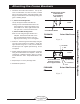
1. After removing the factory steel springs, check
the axle spring perches for side-to-side angle
uniformity. Without disturbing the axle position,
place a magnetic angle protractor on one perch and
note the angle. Next, place the angle protractor on
the other perch and note the angle there as well.
A difference of less than 1° is normal and does
not require a shim. If the difference between the
two angles exceeds 1°, use the supplied 1° wedge
shim to correct the difference.
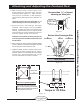
2. Place the 1° wedge shim on one axle spring perch
and re-measure the angles to verify that they equal
less than 1°. Use the centering pin to attach the
wedge to the correct beam and install the beams
as directed in the section titled Attaching the Axle
Beams. DO NOT TIGHTEN FASTENERS until you
have checked the driveline angles as instructed in
the section dealing with that topic toward the back of
this manual.
NOTE: You must check the driveline angles for
cancellation before completing the installation
(see the Driveline Angles section toward the back
of the manual). It may be necessary to reverse the
shim and place it on the opposite side to maintain
correct driveline angles.
3. Measure from the top of each frame rail (at the rear of
the frame) to the ground. The measurement must be
made at vehicle ride height with the vehicle on level
ground and with equal tire pressures. The vehicle
levelness is acceptable if the two measurements from
side-to-side are within
3
/8”. If the vehicle is not level
within
3
/8”, check that the 1° shim is placed properly.
Axle
A 16mm bolt and washer
are supplied for the driver
side only. Use the stock
bolt on the passenger side.
For 4WD crew cab models, refer to the manual
provided with the driveshaft spacer kit # 26029
(purchased seperately) at this time. You must
have this spacer kit before proceeding. If you
do not already have spacer kit # 26029, you can
purchase it by calling Air Lift’s Customer Service
Department at 800-248-0892, extension 1.
5
/
8
"
Flat
Washer
5
/
8
" Nut
U-bolt
Driver-Side Shown
Centering
Pin
Stock Spring
Retainer
Beam